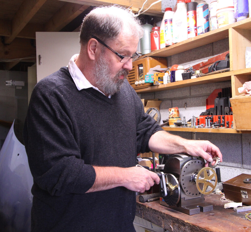
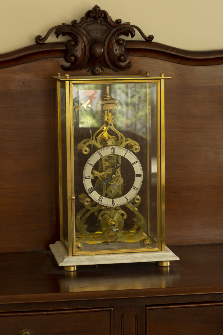
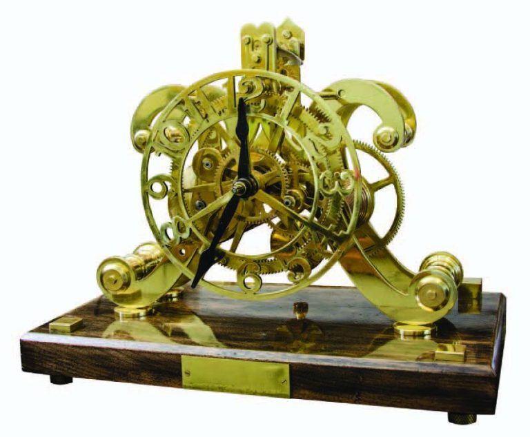
The Shed Logo
Search
Close this search box.

Top gears

Contrary to what the poets say, its gears, not love, that make the world go round. The magic of an exquisitely constructed timepiece with its myriad whirring cogs is an eternal delight. Horology has always fascinated me, and it has long been an ambition of mine to build the mother of all clocks, an orrery. Named for the 4th Earl of Orrery who commissioned George Graham to make the first modern device in 1704, they mark not just the passing of the hours, but the exact movements of the planets as they beat out Kepler’s laws.

Gearing up to make Orrery
By Richard Feltham

Contrary to what the poets say, its gears, not love, that make the world go round. The magic of an exquisitely constructed timepiece with its myriad whirring cogs is an eternal delight. Horology has always fascinated me, and it has long been an ambition of mine to build the mother of all clocks, an orrery. Named for the 4th Earl of Orrery who commissioned George Graham to make the first modern device in 1704, they mark not just the passing of the hours, but the exact movements of the planets as they beat out Kepler’s laws. A horological challenge par excellence, it has to encompass in a single sweep of the dial the 274 years it takes Pluto to orbit once around the sun down to Mercury’s 88 days, a range of three orders of magnitude.

Gears for an orrery

How gears work
Designing the gear train was the first challenge – which meant learning how gears work. The most basic methods of power transmission is by two wheels turning while in contact. Because friction alone limits the amount of power that can be transferred, toothed gears are one way of ensuring that the two wheels do not slip relative to one another when rotating. Pulleys and belts are another. The science of gear tooth design is complex, but boils down to making a shape that will transmit this power with minimal frictional loss and no backlash. This means finding a contour that does not allow relative movement of one tooth’s surface against another during rotation, thus ensuring a constant speed of rotation. A mathematical curve, the involute, is the one we want.

Prototype gears and sleeves

Theory
The most important variable in spur types is the pitch diameter, which is the hypothetical circle at which the gears, if they were just smooth cylinders, would touch. These circles meet at a point on the line drawn between the two centres of rotation, called the point of tangency. The line perpendicular to this point is the tangent line. As the gears turn the actual point at which the teeth touch each other will obviously change, but the wonderfully cunning involute tooth shape dictates that from the beginning to the end of the mesh, this point moves along a straight line, the line of contact. This means that there is no movement of the two teeth relative to each other as they turn, and hence minimal friction losses. The angle between this and the tangent line is the pressure angle. For two gears to mesh smoothly they must have the same pressure angle, usually 200. In reality part of each tooth extends outside the pitch diameter, the addendum, and part inside – the dedendum.

How brass sleeves fit inside each other
Model of George Graham’s original 1704 orrery by, made by Benjamin Martin in London in 1767 and used by 18th-century scientist John Winthrop to teach astronomy at Harvard. (Putnam Gallery, Harvard Science Center. Photograph: Sage Ross)
Richard thinks about cutting gears but...
...Graham Sutton sets up easier Aquajet gear-cutting

Power
Gears transfer power between parallel shafts, giving different speeds by trading angular velocity for torque, as determined by the ratio of our hypothetical contact circles, the pitch diameters. The actual number of teeth is secondary, but obviously you must have an integer number, so in order for them to mesh efficiently at the required ratio the size of the teeth must fit exactly the specified pitch diameter. In imperial terms this is the diametral pitch, and is simply the number of teeth per inch of pitch diameter. The metric world refers to this as the module. Thus a 48 tooth gear wheel with a 6 inch PD has a diametral pitch of 48 ∕6 = 8 and is termed 8 pitch. The same sized gear with 96 teeth has a pitch of 16. It is this concept of pitch that is central to gear train design. If the two centres of rotation are not fixed there is no problem, but if they are constrained as part of the design then it can be awkward obtaining the correct pitch for a given ratio.

Richard burnishes a gear wheel
As the strap is wound around the rod, the red pipe cleaner describes an involute curve. This is the profile of each tooth surface
The point of intersection of the two hypothetical pitch diameters (dark blue dot) lies on a line between the centres of rotation (thick light blue). The thin light blue line indicates the tangent line at 90º. Because of the involute tooth profile, the line of contact (black) is straight, thereby eliminating sliding friction. Pressure angle (arrows) between the tangent line and line of contact is therefore constant, usually set at 20 degrees.

Difficulty
This was the first difficulty I hit. My design incorporates a central tower of independently driven concentric brass sleeves, 1 per individual planetary orbit, each carrying a gear of different pitch diameter, separated by thrust bearings. These mesh with two independent stacks of varying diameter pinions, one for the inner rocky planets, and the other for the outer gas giants. Fixed within each stack, the pinions share a common shaft. This means the centre of rotation of individual pairs of gears is the same, which severely constrains the range of diametral pitch that will work. Brokering Peace in the Middle East is trivial compared to making all these gears mesh properly. I enlisted the help of Mr Meccano in making a jig to hold the parts while I fine-tuned the tolerances. The planet models move on individual rods extending outwards from the brass sleeves. Achieving rotation of the Earth and moon, including precession, requires additional pulley drives. 

Aquajet in action
Partially cut gear

Traditional milling
With 30-odd gears to make, I started out assuming the only practical method available to me was to use traditional milling cutters covering a standard range of pitches. This time-honoured technique uses pre-formed cutters to remove material from the periphery of the gear blank leaving proud the correct tooth profile. A mechanical dividing head calculates the correct rotation of the blank between cutter passes, which is where the next problem arose. Some of the necessary tooth numbers are large prime numbers and are difficult to produce with this method. In addition the profile of the cutter has to be different for each pitch, and to complicate matters further each cutter can only cut a small range of tooth numbers. At around $50 per cutter this approach was going nowhere, fast.

Water-jet cutting
Fortunately in an age of computer profiled, injection moulded, laser cut, web purchased components the opportunity to design and utilize your own gears is accessible to the sheddie like never before. Suppressing feelings of guilt that this was somehow cheating I drew the gear profiles on the computer and emailed them downtown to the local water-jet company, who cut them out of 3mm sheet brass in short order. This technique uses a very fine jet of ultrahigh pressure water to abrade materials. It is capable of cutting almost any thickness of material to a high level of precision, typically around 0.1mm. The cutting software automatically allows for the diameter of the water-jet. I only had to specify the number of teeth, the diametral pitch and the diameter of the internal hole for the water-jet to do its thing. Some filing, burnishing and reaming of the central hole to be a press-fit around the brass bearing sleeves was all that remained to form the central drive mechanism.

The gears in pairs, (from left top row) Mercury, Venus, Earth, Mars, (from right to left, bottom row) Jupiter, Saturn , Uranus, Neptune, Pluto
Earth gear showing thrust bearings
Gearing for Pluto

The numbers
Calculating the requisite ratios was relatively straight forward. I started by assuming that the main motor shaft would rotate once per day. A 90:1 worm gear reduces this rotation down to once every 90 days. For the inner planets a single gear pair then amends the ratio for each planet. Mercury for example has an orbital period of 87.97 days, meaning a ratio of 0.9774 is necessary. The smallest tooth numbers that give this ratio are 89:87, generating an effective ratio of 0.9775. This means an error of 0.009%. The outer gas giants beyond Mars have far longer orbital periods, so a further 90:1 worm drive reduces the overall second shaft rotation to 8100:1. Similar calculations for Pluto require a pair of 12:134 toothed gears to a final error of 15 days in an orbital period of 247 years.
The most complicated part is allowing for the rotation of the moon and inclination of the earth to the ecliptic at 23 degrees. Although I was keen to avoid the need to use compound gearing an epicyclical train is unavoidable here. This is a gear-within-a-gear arrangement, and permits ratios beyond the basic planet’s movement. An arm holding the moon extends from the earth globe. A pulley driven by a fine wire belt then turns this at the correct period of 29.5 days.

Jig made from Meccano

Power
The power is through a very modest little stepper motor, driven by our old friend the PICAXE, programmed to turn the main drive shaft through the necessary one complete revolution in 24 hours. A single pulse every 213 seconds achieves this. The programmable stepper provides the ability to advance the orrery to correct any accumulated errors, or every time NASA moves Jupiter by employing gravity slingshot manoevures. Also it means that it can reproduce the planetary positions on any given date.
The frame is a brass rod cage mounted on a circular rimu base. A central ‘sun’ carries the hour hand. A detachable outer ring, against which the Pluto model moves, will have engraved signs of the Zodiac and family birthdates. We can add future generations as they come along.
And I don’t care what they say, Pluto is still a planet.

Richard’s granddaughter Iris and Pluto wheel. Family names will be recorded around the orrery

Gear types
Although numerous gear forms exist, ranging from external and internal spur types to helical and worm varieties, they share common properties. For any given gear diameter you can obviously have a few big teeth or lots of little ones. Equally clearly, for two gears to mesh smoothly the teeth must be the same size and profile on each wheel. The critical variables for a simple spur gear include the overall diameter, as well as the size, number and shape of the teeth. 
Helical gears, like those found in power drills, are a variety of spur and follow similar rules. Worm gears allow power transmission at 90 degrees and permit far wider ratios, up to several hundred to one, but only permit transmission in one direction. Other specialist applications, like the hypoid gears in a car differential allow non-parallel shafts to mesh at any angle.

Worm drive
Computer printer gears

Share:

More Posts

A matter of time

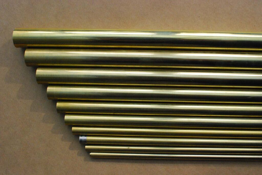
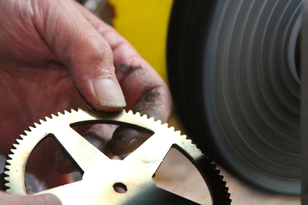
I purchased all the brass sheet and rounds required, plus a main-spring, brass bolts, and screws of the various sizes needed.
Now where to start on the clock?
I carefully read and followed the order and instructions of the book. If the instructions are not adhered to, many anxious moments and frustrations will follow.

Turning out a crescent clock

A crescent clock looks at its best if it is made from a stylish native timber.
For this project, I used a kauri block. When you come to select the wood which will be prominently on display in the living room or dining room, for preference choose a piece of timber that has a distinctive grain.