Building a hobbing machine and Lyre and Strutt skeleton clocks
By Brian Wiffin
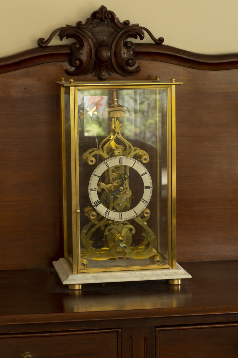
The Strutt’s epicyclic skeleton clock
Brian Wiffin in his current workshop with his newfound passion—clocks
Brian’s workshop in Dannevirke
Unique mechanics
The Strutt skeleton clock is one of the most interesting of all single-train skeleton clocks ever conceived. First made by Englishman William Strutt, it has a number of interesting and extremely unusual features not found in other clocks.
Its eight-day run, spring-driven train is epicyclical (planetary gearing) and involves a ring wheel of 4½ inch (114 mm) ID and 5½ inch (138 mm) OD teeth. The motion work is based on the Ferguson Mechanical Paradox Orrery instead of the normal 12 to 1 gear train. The collets are unusually designed to allow the individual setting of the hands. This clock is an excellent timekeeper as well as being beautiful and unusual.
The centre arbour carries the minute hand and is driven by a fusee/ great-wheel assembly. Fixed to the centre arbour is a planet arm with a counterweight on one end and a planet wheel and pinion on the other end. A sun wheel is fixed to the dial and cannot rotate. The planet pinion engages this wheel and is forced to rotate while being moved around it by the planet arm. The planet wheel drives the internal teeth of the ring wheel, which is free to rotate on the centre arbour. The external teeth of the ring wheel drive the escape wheel pinion. A conventional recoil escapement drives the pendulum.
William Strutt designed his epicyclical geared clock in the late 1820s and his friend William Wigston built it. Because of the difficulties involved in making epicyclical gears, very few were made by Strutt and Wigston. The visual fascination of epicyclical gearing (also more commonly referred to as “sun and planet gearing”) has subsequently inspired many copies of the clock. Epicyclical gearing has been used in orreries and is extensively used in transmissions for all sorts of machinery, including cars.
How To Make A Strutt Epicyclic Train Clock by master clockmaker W.R. Smith demystifies the logistics of how these clocks work and how to build one.
Making a clock had never been on my “to do” list.
My retirement project was to build a 7¼ inch gauge steam locomotive and join the Palmerston North Model Engineers’ Club members on their lovely track. However, selling my engineering workshop and house in Dannevirke in 2007 and retiring to Matamata to a lifestyle village put paid to these plans. I had no inkling at the time that I would embark on a major learning curve making a clock and that it would be just the start of my journey exploring the intricacies of building them.
Over the years before I retired I built up a very good engineering business, even though all my skills have been self-taught. I never served any apprenticeship nor had any engineering qualifications but I managed to get a lot of outside work. I was born on a farm in the southern Hawke’s Bay and was 15 years old when I went to work for my grandfather in his concrete products business.
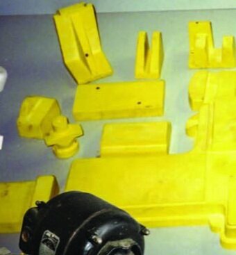
When the demand for concrete products waned I worked for a time as a carpenter and then as a rural mail delivery contractor and I began to think seriously of my future. I started to put together an engineering workshop while my wife Margaret and I operated the mail run for 23 years. I had my first taste of engineering when I was in the concrete business and found no firms wanted to make strainer moulds, so I said I would.
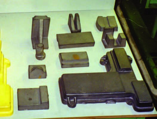
I bought a Young Arc Welder, purchased the steel, a Palmerston North firm did all the pressing I needed and I did the rest. It took me 12 months of my spare time to make nine moulds but they worked superbly. While I was still working as a postie, I bought an old Wilson metal lathe which I used for 10 years. In 1981 I took the plunge and bought a brand new English Colchester Master 2500 lathe. It arrived on 31 August and was the best birthday present I’d ever received—even if I did buy it myself!
I used this lathe for 25 years and it was just as good when I sold my business in 2007. Over the years, I purchased several old machines which I enjoyed pulling to pieces, doing up, and repainting. I bought an old 18-inch (457 mm) shaper, a large milling machine, a surface grinder, a cylindrical grinder, a drill sharpening machine, and a tool and cutter grinder. I made my own hydraulic press, a gear hobbing machine, and tooling for my machines.
The hobbing machine Brian built himself
The hob cutting a gear
Gearing for the hobbing machine demonstrating the variety of gears that can be cut
A selection of hobs
Building a hobbing machine
In June 1999 my copy of the Model Engineer’s Workshop arrived and on the cover was a picture of a small Jacobs Gear Hobbing Machine made from castings.
I read this article and thought it would be an interesting project to make and be handy in my workshop. I had been a member of the Palmerston North Model Engineering club for 10 years and at their next meeting I mentioned that I was going to make the machine that was described in the latest magazine.
Two of my friends at the club, Finn Mason and Bill Morris, said they would also be keen to join in this project so I sent to England for the plans and priced the castings. The cost to send the castings to New Zealand was prohibitive so Finn, who was a draughtsman, told me to only get the plans and he would make a set of patterns which we could then get cast at the local foundry.
We discussed what each of us could do. Finn made the patterns, Bill would machine the worm and pinions, feed screws, and nuts. I would machine all the castings, etc, as I had all the necessary machines. Once the patterns were made, we got four sets of castings done, with one extra to sell to defray expenses.
When the foundry in Palmerston North had made the castings, the 40 pieces of grey cast iron came out beautifully and were lovely to work with.
Fitting the clock spring into the spring winder—another tool Brian has built for himself
Gear wheels
Over the next 12 months, I machined all these pieces.
First I did the large base castings in the shaping machine, then milled, turned, and surface ground all the other castings as per the plans. By this time Bill had made all his parts so it was getting close to fitting and assembly time. I chose to work on and finish my machine first so that if there were any teething problems they would be sorted and make the assembly of the other three machines easier.
There are lots of gear wheels that have to be made for this machine and the gears were based on Myford lathe change-wheels, 20DP x inch (16 mm) bore. So when my machine was nearly finished, I borrowed Finn’s Myford lathe change-wheels and put them on my hobbing machine. I made my first hob 20DP and backed off the teeth nearly to the cutting edge. I could not make a form-relieved hob so this backing off was done so that the teeth of the hob did not rub.
Next to make was lots of cast-iron gear blanks for all the different-sized gear wheels needed—about 20 for each machine. By this time 18 months had passed since we had started the project and, with the lathe change gears in place, it was time to cut my first gear.
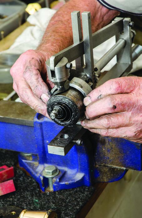
Pushing the spring into its barrel with the mill drill and custom-made die
Fixing the end caps to the spring barrel
Winding the spring to engage the main spring hook
The completed spring barrel
Attaching the clock face mounting bolt that can’t be placed after the barrel is positioned
Greasing the bearings for the barrel
Mounting the main spring
First cut
The instructions for setting up were first class.
I set up the gear train for the correct number of teeth required and mounted the blank on an arbor. I started the machine and lowered the blank very slowly until it just touched the hob, set the dial at zero, wound back the blank from the hob, and lowered the blank one-third of the required tooth depth.
I made three passes lowering the blank, the same each time until the required depth was reached. The first time was a little scary but it worked fine and as I cut more gears I quickly got used to the noise and action. As the machine drives the blank across the hob, all one really needs to do is watch the teeth being generated. I cut all the gears required for the four hobbing machines at this stage of the project and returned the lathe change-wheels to Finn.
The four hobbing machines were nearly finished with only the assembly of the other three to be completed.
Mounting the fuse
Mounting the central arbour and pinion
Attaching the rear frame
The epicyclical gear train
No hobs
There was only one aspect of making this machine that worried me and that was I would have a machine but no hobs.
I had been looking around the world for hobs but they were expensive. One hob will cut any number of teeth in the pitch for which it was made. A model engineer friend who had his own engineering business had built a similar hobbing machine and on a visit to Japan brought home two small hobs to cut the timing gears for a small model petrol engine. I had no idea how I could get any of these hobs but another model engineer had seen an advertisement in an English magazine for a set of nine module hobs from .3 to 1.25 pitch. I ordered a set and they arrived six days later.
They are of Chinese origin, are high-speed steel, and are beautifully made. I have used most of them and they have not yet lost their cutting edges. The actual article was a Ces Gear Hobbing Machine based on the original Jacobs Gear Hobbing Machine.
The College of Engineering, England, put out the plans and castings for the Ces machine and this is the machine I built. This was a very interesting machine to build and I still have the plans, patterns, and instructions for setting and cutting the first gear.
The ring wheel is slid onto the central shaft
The clock face with the epicyclic gear train and the paradox movement for the hour hand
Making a lyre skeleton clock
After I retired and went to live in Matamata, I missed my machines and, as I like to potter and need something to do, I set up a small workshop in half of the garage. I fitted it out with two long benches complete with drawers. I had W.R. Smith’s How to Make a Lyre Skeleton Clock book and the clock looked nice so I decided to make one. I knew absolutely nothing about clocks but I like a challenge. If I finished it, there would be a nice clock to grace our lounge. Little did I know what I was letting myself in for or I may never have started the project. Bill Morris, who had made two clocks, said I would have problems as clocks have to be loose, with no friction, etc. How right he was.
Where to start?
I purchased all the brass sheet and rounds required, plus a main-spring, brass bolts, and screws of the various sizes needed.
I bought a small lathe, drill mill and a band saw. I brought my hobbing machine and tool and cutter grinder to Matamata so I was able to keep my cutters and drills sharp. Now where to start on the clock?
I carefully read and followed the order and instructions of the book. If the instructions are not adhered to, many anxious moments and frustrations will follow.
The two plates were made first as everything else is attached to them. After the plates, I machined the feet, the pillars, and the decorative washers. All are then brought to what I call half-finished. I leave the final fine sanding and polishing till after the clock is completed and running as this saves being scratched if it has to be disassembled.
I have made two Lyre clocks successfully now and having recently bought a book on How to Build the Epicyclic Train Strutt Skeleton Clock, also by W.R. Smith, I have begun making the new design. The assembly of this clock is documented here. I had built and tested this version and taken it apart for final polishing.
Fitting the face
Tightening the collars on the central arbour.
Assembling a Strutt skeleton clock
First I laid out all the clock parts in the order of assembly. I bolted one mainframe to the four pillars.
One of the clock-face holding bolts was placed in the frame facing out. This bolt is behind the mainspring barrel and cannot be put in place later. The small stop spring is now bolted on inside the mainframe, as is the small stop-arm bracket.
The barrel—complete with arbour and spring and the fuse assembly— are now placed in their respective pivot holes. The other clock frame is now fitted over the protruding axles and pillar ends. At this time the centre arbour and its pinion are placed in position, making sure that it is in mesh with the great wheel.
When all is in order, the frame bolts and decorative washers may be fitted and both sides tightened up securely.
The next stage is to slide the small and large collars on to the centre shaft. This is followed by sliding the ring wheel onto the centre shaft. The large collar is slid onto the ring wheel boss. These bosses will be locked in place later. It is now time to fit the clock face.
Four spacers had already been fitted, along with the paradox movement for the hour hand and the epicyclic gear train and pinion. This unit is now carefully fed onto the end of the centre shaft and the gear wheel is put into mesh with the inside teeth of the ring wheel. The bolt already in the frame and three others hold all this assembly in the correct place. As these bolts are done up, it’s important to make sure that everything turns nice and freely. If there are any binding or tight spots, now is the time to sort out these problems.
Checking everything runs freely
Fitting the escape wheel and pinion
Checking the escape wheel arbour is square
The anchor and pendulum crutch arbour
Winding the fusee
The end of the fusee wire fixed to the spring barrel
Escape wheel
With this part of the gear train all running nice and freely the next stage is to fit the escape wheel and pinion arbour.
This shaft fits high in the frame and a small adjustment bracket is bolted to support the small pinion end. This pinion meshes with the outside teeth of the ring wheel and must be very carefully adjusted so it runs very freely and smoothly. Lock up the screws in adjusting the bracket.
The last arbour to be fitted holds the anchor and pendulum crutch. This is mounted in the top pivot hole and the pendulum end has a bolt-on bracket with a small cam for the pivot. This will allow a small adjustment between the anchor and escape wheel.
The clock is now placed on its wooden base and fixed with four nuts. The pendulum and rod are then bolted to the small bracket, making sure both are perpendicular.
Fit the two hands on their respective arbours. Now it is time to set the clock going. First, the fusee wire is carefully wound onto the fusee and the other end is placed in its mounting hole on the main-spring barrel. The main-spring is now fully wound and then backed off 1½ turns.
Set the pendulum in beat and make any adjustments to the anchor and escape wheel depth by the small cam to get the clock running properly. This may be a trial and error session, especially on your first clock. If the clock is running fast, adjust the pendulum screw down. If it is running slow, screw it up.
Happy clock making.
Setting the pendulum…
…and setting the hands
The finished clock
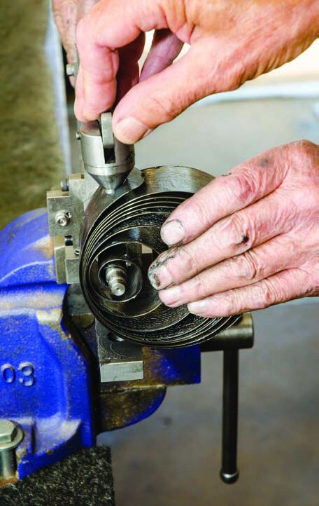
Winding-up
One of the most fraught processes in clock making is fitting the main-spring into its barrel.
The spring for the Strutt clock is around 8 feet (2.5 metres) long. It fits in a barrel of only about 3 inches (76 mm) diameter.
You need a clock spring winder to get it into the barrel. The spring is first cleaned, then greased and the inner end is fitted to the clock spring arbour. This, in turn, is fitted into the winder and the spring is compressed to the point where the mainspring hook can be engaged.
The spring is then carefully wound to the point where the keeper can be placed around the spring. The keepers are made to accommodate the main-spring barrel you are using.
The spring is then released carefully until it fills the keeper and both the spring with its arbour and the keeper are detached from the winder. The keeper is set over the barrel. Brian uses the quill of a mill drill to push the spring into the barrel using a custom-fitted die.
Once in place, the end caps are fitted and the spring can be rotated to engage a hook set into the barrel with the holes in the mainspring.