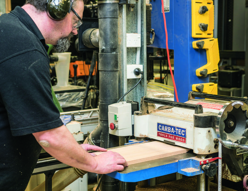
While we are rather spoilt these days for ready sources of energy, it was once a matter of harvesting what was available in the local environment. More often than not, what was available was a stream or river, and so the workshop was built on the riverbank and the harvesting was achieved by a water wheel.
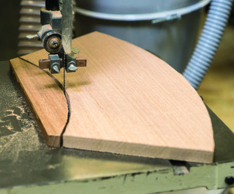
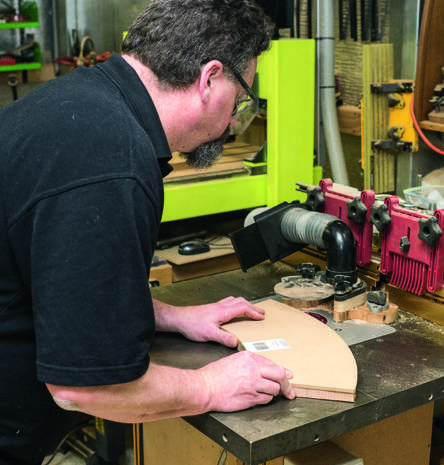
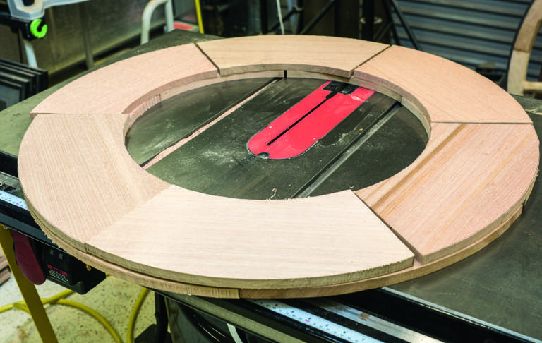
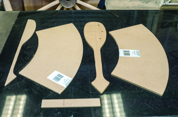
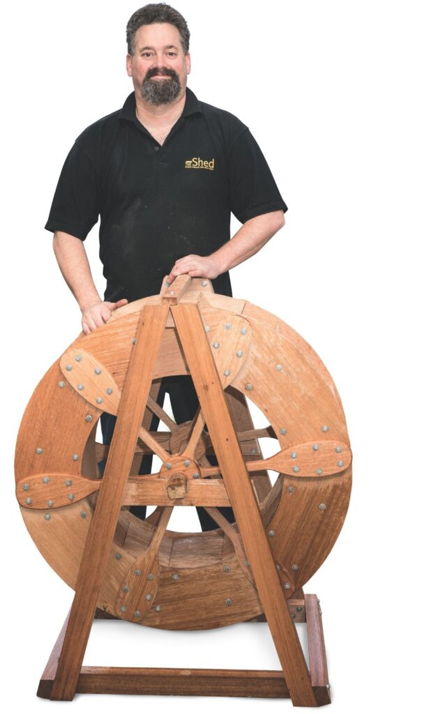
I’ve always been rather taken by the concept of water wheels (and other mechanical devices that harvest energy from nature), and have been intending to make a small one of my own, even if it was just to be a garden ornamental feature.
You may well ask, just how many ways can you actually make a water wheel, and the more I thought about it and the more research I did, the more surprised I become about the breadth of the topic. I found a particularly interesting reference, quite the authority on water wheels. It is “The Engineer’s and Mechanic’s Encyclopædia: Comprehending Practical Illustrations of the Machinery and Processes Employed in Every Description of Manufacturer of the British Empire”![]() by Luke Herbert, and the title is quite the mouthful. Interesting to find a book that has such a strong understanding of the science of water wheels. Of course, that it was written in 1836 might have something to do with it!
by Luke Herbert, and the title is quite the mouthful. Interesting to find a book that has such a strong understanding of the science of water wheels. Of course, that it was written in 1836 might have something to do with it!
When planning on a water wheel, the type is heavily dependent on where the energy is coming from. Where water is available at a height, then it has potential energy that can be harvested as the water drops. The theoretical maximum available is mass x gravity x height. (Theoretical, because there are always losses in the real world).
Where water is flowing/moving (such as a stream), then there is kinetic energy available, from the force of the water hitting each blade of the water wheel. In this case, the energy is equal to ½ the mass x the velocity2.