Channel your childhood heroes to a new generation by making this toy Sopwith Camel.
By Stuart Lees
The finished Sopwith Camel…a toy with a history
I am probably showing my age, but I grew up with comics following a certain beagle, who was rather taken with imagining himself as a World War I fighter pilot dueling with the Red Baron.
There were also books handed down from my father following the fictional World War I heroic pilot, Biggles.
For both Snoopy and Biggles, their vehicle of choice was the Sopwith Camel, a rotary-engine-powered biplane, with twin Vickers machine guns, which for much of the war was the deadliest plane in the air. What better way to introduce a legendary aircraft to another generation than through the universal medium of toys? While there are a number of limitations in a toy around scalability, safety, and complexity, I wanted to still give a firm nod in the direction of the original inspirational aircraft. A search of the internet yielded some basic plans of the original plane and images of recreations of the Sopwith taken from various angles.
Shooting straight
The roundel has an interesting history and dates to just a couple of years before the Sopwith Camel.
Early on in World War I, ground forces fired at any aircraft, friend or foe. Bit of a bad idea being shot at by your own side, especially when sitting in an aircraft made from not much more than balsa and cloth!
The British started with the Union Jack, but at a distance, the cross of the Union Jack and the cross of the German Iron Cross were easy to mistake. After a few iterations, the roundel that is still used today was arrived at, and its 1:2:3 proportions were also set.
On the tail section of RAF aircraft, they also had a flash of the same colours, so that is also what I wanted here, made from the same timbers as I used for the roundels
Design
The next step was to make some sketches to get an idea of how it may look in practice and how to translate the design into something that would be effective as a toy.
A concept quickly emerged of creating a T cross-section that gives the fuselage some bulk without making the whole thing too heavy, or the build too complicated. While I tried to maintain the proportions to a certain degree, it also had to have the more stylised (and practical) proportions of a toy.
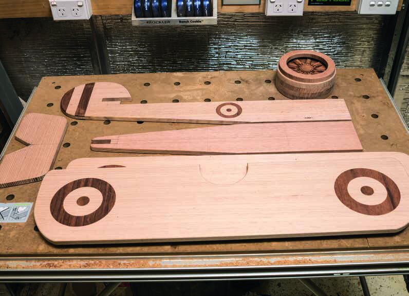
The sketches developed into paper cut-outs, which is not something I normally do, but it proved to be a really effective approach in this case. I could scale individual items to fit the design, work out overlap, and where items would lock into each other. There was one decision that I made without having to think about it—I prefer my wooden toys to retain the wooden finish: painting was not an option. If I was going to make something with a painted finish, it might as well be made from MDF.
With photographs of the real deal for inspiration the design progressed from diagrams, to paper cut-outs through to work on the upper wing.
Starting the build
So where to start? The upper wing—it dictates the size of the rest of the project and with very little work it takes on its final form, so you can quickly visualise how the project will look.
I first took a piece of 3 mm MDF and sketched out the particular curve of the wing edge. This was then cut out on the bandsaw and sanded to the final curve. Having a template meant I was able to trace the exact curve on either end of the wing.
MDF is a great material for templates. It is cheap, easily machined and shaped and, when attached to the timber, can be used as a guide for a template-copying router bit. For tricky sections, you can make some test pieces in MDF before committing to the expensive and limited supply of quality timber. When the build is finished, the MDF templates can be stored for future reference.
Before cutting out the wing shape, there was one other job to do which is made easier by having the additional waste timber around the outside of the wing still available. I wanted to have the roundels on either end of the wing made from contrasting timber inlay.
Initially, I was going to only put the roundels on the top of the upper wing—after all that is the surface that is mainly seen on the toy. However, I really wanted to lift the project further (and in time, that may be just what happens), so the underside roundels on the lower wing were added and one on either side of the fuselage.
Cutting an MDF template of the curve of the wing on the bandsaw
Using an inlay kit and handheld router to make the roundels
Inlay techniques
The roundels were created with a handheld-router using standard inlay techniques.
I have the Whiteside Inlay Kit, which makes the process surprisingly easy. To start, you need a template for the design you want to inlay. These can be purchased, found (many a paint can has been used to draw circles for example), or made.
Given a roundel is circular, cutting an MDF template on the bandsaw with a circle jig produces circles of the required diameters. The template and workpiece are attached together and double-sided carpet tape is particularly suitable for this.
With the inlay kit mounted to the router and the brass ring from the kit in place, the cavities in the wing are routed out. I chose to make the cavities 5 mm deep, so the inlays have some thickness and strength before they are hammered into place. I can also sand the resulting wing a bit without worrying about sanding right through the inlays.
The same template is then attached to a piece of contrasting timber. With the brass ring from the kit now removed, the outline for the inlay is routed. I made this 6 mm thick, so the inlay would initially sit proud of the surface so it can be sanded flush. When creating the inlays, they are cut into timber thicker than what will be the desired result.
Once the outline of the inlay has been cut, it needs to be released from the surrounding material. I did this by first re-sawing the board on the bandsaw, getting its thickness down to near the final dimensions. To then release the inlay, I sanded with 80-grit sandpaper on a random orbital sander (ROS) until the outline of the inlay became apparent from the underside and continued until the inlay was fully released. You can use a belt sander for this, but be very careful not to turn your inlay into a wedge, very thin on one edge!
To insert the inlay, it is a good idea to first relieve the edges on the lower side of the inlay. This can be done with a few swipes with a piece of sandpaper and makes aligning the inlay with the cavity a lot easier. A small quantity of glue is applied into the cavity before the inlay is put in place and gently encouraged into the cavity using a wooden mallet.
It is best to start with many light taps over the whole surface of the inlay before increasing the amount of force used to drive the inlay home. Sanding the inlay flush with the surface can also be done with a belt sander if you are careful (or have a belt sander with a sled, such as the Festool), or with a random orbital sander with 80-grit paper. The result is quite stunning and yet a lot easier to achieve than the future admirers of the toy would imagine.
The cavity for the inlay is routed 5 mm deep
One roundel completed and inserted gently with a bit of tapping from a wooden mallet
Wing outline
The wing outline is cut on the bandsaw, using a thin ¼ inch (6.35 mm) blade.
The thin blade makes it easy to cut curves very close to the desired line. From there, the curved wingtips are smoothed out by a disc sander. If the disc sander cannot get inside an area (such as the concave opening in the middle of the upper wing), then the oscillating spindle sander takes over.
Then it is over to the router table to run the part over a round-over bit to make the edges kid-friendly by removing any chance of incurring splinters. The lower wing is a duplicate of the upper, at least to start. The roundels are underneath the lower wing, so if you never intend to have the toy above ground level, you can save a bit of work by omitting them.
The Sopwith Camel had a straight upper wing, but the lower had a 3-degree dihedral angle (where the wings rose slightly from fuselage to tip). You may choose not to incorporate that feature—it makes the build quite a bit more complicated and weakens the lower wing (having to make it from three parts). For a child’s toy, strength is a factor, so with a bit of regret, I chose to ignore that feature of the original aircraft.
Smoothing the wing profile on the disc sander…
…then over to the router table to make the edges kid-friendly
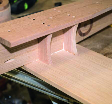
A couple of slots in the tail engage with the body and a second holds the rear wing.
Aircraft body
The body of the aircraft doubles as the seat for the toy and includes the tail section.
A couple of slots in the tail engage with the horizontal portion of the body and a second slot holds the rear wing. The tail itself has the identity flashes and roundels of inlay timber inserted in either side.
The top of the body section is tapered to remove some of the visual weight from the design and to give the plane a more streamlined look. The engine is an area where some features can be incorporated that really set this design apart from simpler (and similar) toys. Making a substantial engine cowling takes the whole toy from being a few flat pieces of board joined together and transforms it into a fully three-dimensional design.
While you could turn the cowling on a lathe (it could be thought of as a large bowl after all), it is easily made by cutting wooden rings and gluing them together. The rings can be cut by a number of methods, including jigsaw and scroll saw, or by using the same technique as we did for the inlays, but my favourite method is using a homemade circle-cutting jig on the bandsaw. It does have one disadvantage—it results in a thin cut through the ring, but that is easily hidden at the bottom of the cowling.
The jig involves a flat board that is restricted to slide in one direction on the bandsaw table. This is either achieved by having a small piece of timber underneath that engages the mitre slot on the bandsaw table, or a couple of pieces that fit around either side of the table.
One final piece stops the board sliding beyond the half-way point. While making the jig, start the bandsaw with a ¼ inch (6.35 mm) blade and slide the jig into the blade until it stops on the stop-block. Remove the jig and draw a line perpendicular to the saw cut at the point where the cut ended. Measure the radius that you want the circle to be and hammer a small nail into the line at that point.
With some end cutters, clip off the head of the nail, leaving only about 5 mm protruding. This is the pivot point. Take the piece of timber that you want to make circular and push it onto the pivot point. The piece of timber should be able to be rotated freely on the pivot point and should overlap the end of the saw cut during the entire rotation.
Holding the board firmly, start the bandsaw and slide the jig and attached piece of timber into the blade until the jig stops on the stop block. Simply rotate the piece of timber into the blade around the pivot point, cutting a perfect circle. Once each of the required discs are cut, change the pivot point location to a smaller radius (ie, pull out the original nail, hammer in a new one and cut the head off this new nail) and cut the inside of each ring. One ring is slightly smaller diameters on both the inside and the outside. This is the front of the cowling.
Using the circle jig on the bandsaw
Rotate the piece of timber into the blade around the pivot point to cut a perfect circle
One of the discs is left solid
Rotary engine
One of the discs is left solid. This allows the cowling to be firmly secured to the body of the plane and provides a solid connection point for the prop.
It also provides an opportunity to make a bit of an engine in a nod towards the nine-cylinder rotary engine of the original. There are a few ways you can approach the engine. One method is to take a large piece of dowel, cut off slices to create each cylinder, and simply glue them on. You’d get two cylinders from each section of dowel.
If you have a lathe, you could take this a bit further and give a nod towards the air-cooling fins on each cylinder before cutting off each vertical cylindrical segment. If you have access to a CNC router, you could go with a full-blown, 3D-carved rendition of an engine. I’ll leave it to you to work out which option I chose to go with.
A threaded insert was screwed into the front of the engine so that a bolt could be screwed right through which will become the shaft for the prop. The insert is threaded inside and has very coarse fins on the outside that cut into the timber as it is screwed home using a hex key.
Smart turn
The rotary engine in the Sopwith Camel gave the plane one of its real quirks. The torque of the engine (and being a single prop) meant the plane turned slowly to port (left), but was able to whip around when turned to starboard (right). In fact, the Sopwith Camel could turn twice as fast as its contemporaries, which is an obvious advantage in dog fights. It was so quick turning to the right that if a pilot wanted to go left, they would often do a 270 degree turn to the right, rather than a slower 90 degree turn to the left!
The threaded insert screwed into the front of the engine
Plane assembly
With the main components created, it was time to start building the plane as the dimensions of the outstanding components depend on how the ones made so far come together.
The horizontal fuselage is attached to the vertical part (that incorporates the tail section). I used glue and screw for this project. I am not keen on using screws at the best of times, but a kid’s toy needs strength and screws can significantly increase the strength of a joint. The rear wing is then glued and screwed into the slot in the tail. Next, the lower wing is glued and screwed underneath the fuselage. A couple of gussets are attached to significantly strengthen the wing’s attachment. This is especially important as the undercarriage also attaches to the underside of the lower wing.
The brackets screwed to the undercarriage and the axle and wheels fitted
Upper-wing bracing
The upper wing on the Sopwith Camel sits quite a bit further forward from the lower wing.
This creates an unusual situation where the outer supports for the wings are set at quite an angle. This provides an advantage for the toy as it means the lower wing is an easy footrest for a smaller child. It proves to be quite a bit harder for the toymaker though.
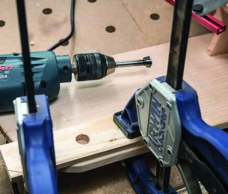
To start, I chose a Forstner bit that matched the diameter of the dowel I chose to use for the braces. I needed a jig to guide the Forstner bit as they cannot drill at an angle easily when mounted in a drill press and cannot do so if in a handheld drill.
To create the jig, I drilled straight into a 4 x 2 (47 mm x 40 mm) block of timber. Next, on the tablesaw with the blade tilted over, the top and bottom of the block were ripped away so the hole was then at the required angle.
By clamping this jig in the required location, angled holes could be drilled with the Forstner bit. After temporarily fitting the four main wing supports, the locations and lengths of the extra supports from the fuselage were worked out, then drilled. I kept them at the same angle (using the same jig) but, as with the original aircraft, these are angled at 90 degrees to the main braces. With the braces all glued in position, the upper wing was then attached.
I was considering making a mock-up of the cross-bracing wires by using thin dowel, but a combination of time pressure and the fragility these dowels would have for a kid’s toy made me have second thoughts. Looking at the resulting toy, this was the right call. The engine and cowling were attached to the front using glue and pocket holes. Pocket holes are a joinery technique based around screws, but with a difference—the holes for the screws are set at a steep angle and are drilled with a pocket-hole jig (like a commercial version of the jig used for the dowels, come to think of it).
The undercarriage was made with a couple of pieces of timber, cut at angles as a nod towards the original. After each was cut, a pocket hole was drilled into the back edge of each so it would be easy to attach to the bottom of the plane when the undercarriage was completed.
Brace and prop
A horizontal brace was added, again with pocket holes on the underside, creating a rigid frame.
I purchased some wheels that looked the part and had needle bearings so they ran freely. A commercial toy vehicle axle was available to match the wheels and it came with all the required items—split pins, end caps and brackets.
These brackets were screwed to the underside of the undercarriage and the axle was fitted, along with the wheels. This was then screwed and glued to the underside of the wing.
The rear wheel is a castor, so this was simply screwed in place, with a couple of support blocks on either side. With the project nearing completion, I could then work out just how long the prop needed to be to look right.
Using the MDF template technique again, half the prop was sketched then cut out on the bandsaw and sanded smooth on the disc and spindle sanders. This was then transferred onto a piece of kwila, then the same process followed of drawing the outline (using the template), cutting on the bandsaw, then sanding smooth.
Like all the other parts in this project, it was rounded over using a round-over bit on the router table. With the prop bolted to the front of the engine (with a piece of dowel used as a spacer, like a glorified washer), the build was complete. Finishing will be done at another time, firstly by sanding, oiling to get the quality of the timber to pop, and to get the contrasting timbers to really come to life, then a protective finish applied over the top of that.
The finished Sopwith Camel ready for play
Play time
The Sopwith Camel toy is large enough for a small child to ride, so it can be used in a number of ways.
I originally intended that it would be suitable to use as a rocker and, by making a basic base, the plane could be fitted to it and used in this way for younger children.
It is also intended to be lifted clear of the rocker and used as a ride-on toy. This can be done a couple of ways, with a tow rope that older children can pull, or with a long handle attached to the rear that a parent can push.
With additional seating and some securing methods (harness) for the child, the plane could be turned into an incredible swing so the plane could, as a manner of speaking, fly. I didn’t add handles to this project, but if it is to be used as a kid’s toy, you can cut out a couple of handholds at the rear of the upper wings. If the toy is expected to be used outside, then ensure a waterproof glue is used during the build.
If it is only ever going to be an internally-used toy, then yellow PVA is quite sufficient. This was a particularly fun project and can be tailored to your individual skill level. Once you’ve made this project it wouldn’t take a lot to modify it, changing the relative wing positions between layers and adding a third wing. Thus the original battles between British pilots and the German Red Baron can be re-enacted once again.
Materials used:
• 7 x 900 mm x 230 mm x 17 mm Victorian ash hardwood
• 2 x 900 mm x 230 mm x 12 mm kwila
• 1 x 500 mm x 90 mm x 22 mm kwila
• 1 x 300 mm x 150 mm x 12 mm spotted gum
• 1 x 2400 mm x 25 mm diameter Victorian ash dowel
• 2 x 90 mm diameter wheels
• 1 x 50 mm castor wheel
• 1 x toy axle kit
• 1 x 90 mm coach bolt
• glue & screws