The Shed Logo
Search
Close this search box.

Milling – showing restraint

In Part One of this series on the milling machine we put the milling machine in the workshop and had it levelled. Before you use the machine, it is important to check the alignment of the spindle. Then comes understanding the importance of preparing the workpiece. Work to be milled or drilled on the milling machine has to be set up so that it does not move during the job. This is one of the most important things you can do if you don’t want an important component or workpiece to end up as scrap because it moved.

Part two of our milling machine series: restraining movement
By Peter Woodford
Photographs: Geoff Osborne

Round bar firmly restrained by clamps with heel / packing blocks, vee block and parallels (behind drill) as fixed abutments

In Part One of this series on the milling machine we put the milling machine in the workshop and had it levelled. Before you use the machine, it is important to check the alignment of the spindle. Then comes understanding the importance of preparing the workpiece. Work to be milled or drilled on the milling machine has to be set up so that it does not move during the job. This is one of the most important things you can do if you don’t want an important component or workpiece to end up as scrap because it moved.

Six degrees of freedom
Every component, no matter its shape, can move in six ways — up, down, sideways, left or right, forwards, and backwards — and rotate around these axes. The piece has to have these movements restrained for machining. Generally, we don’t give enough thought to how we hold a workpiece.
We can make sure to restrain all these “six degrees of freedom” by getting into the habit of looking carefully at every workpiece to consider how the clamping set-up is going to cope with the cutting forces.There are two ways to accurately position every workpiece and secure it. They are:
• Fixed abutments (solid supports or rests); and
• Friction (clamps).
Restraint of movement is achieved by a combination of these two methods.

Plate only clamped. A drill grabbing may overcome the friction restraining the plate

“Consider how the clamping set-up is going to cope with the cutting forces”

Clamping
Securely clamping a workpiece before machining is the part of this process you have the most influence on. The more rigidly you can clamp the workpiece the more material you can remove at one time, and it’s less likely workpiece-induced chatter will occur.
You need to clamp a workpiece securely but not so hard as to damage it. But before you start clamping any workpiece, you need to assess:
1. What machining processes are going to be used?
2. Where on the workpiece you are going to be machining?
3. What order of machining will you use to achieve the finished product with the minimum number of set-ups?
You must also consider the cutting forces that are going to try to move the workpiece out of position. If you are getting unwanted movement of the workpiece, tightening the vise or a clamp bolt may not be the only answer. A review of your set-up and the better positioning of a clamp, adding another clamp, or using a fixed abutment to overcome the cutting forces may be far better and often safer.

Stops at edge of plate act as fixed abutments to prevent plate rotating

Placing
By placing the workpiece onto the bed of the machine (a fixed abutment) you have started to reduce the degrees of freedom. If you place the workpiece into a vise, the base and the fixed jaw of the vise provide fixed abutments and so reduce the degrees of freedom. When you tighten the vise, the clamping forces restrain some of the other degrees of freedom through friction.
For a simple component, support from the base and fixed jaw and the friction applied by the moving jaw will be enough. When things get bigger and more irregular in shape, the same rules apply. By a mix of fixed abutments and friction, any workpiece can be positioned and held securely.
Always consider fixed abutments first. These are not going to let your workpiece move. Any freedom you restrict by friction or clamps may be overcome by the cutting forces, especially if the workpiece cannot be clamped with much force if, say, it is of thin section. Next, we take some examples of restraining components or workpieces.

Drilling inside vice should present no issues
Plate only clamped. A drill grabbing may overcome the friction restraining the plate.
Screw jack abutment provides support

“When things get bigger and more irregular in shape, the same rules apply”

Plate
Consider a plate that needs a large hole drilled in the centre. It is too big to go in the vise, so you place the plate on the bed of the milling machine and pack it up. This stops you from drilling into the bed of the machine when the drill breaks through. You position the clamps to secure the plate and not interfere with the drilling.
The principles here are that the bed of the machine and the packing act as a fixed abutment to deal with the downward drilling forces. On the other hand, the friction applied by the clamps restrains the other force — the rotational force exerted by the drill.
But if the drill bit grabs, the momentary increase in the rotational force may be enough to overcome the friction applied by the clamps. At this point, things can get very interesting.
The whole set-up may instantly part company. You now have clamps knocked out of the way and a plate whizzing around at the same speed as the drill. During this mayhem, you have to hurriedly switch off the machine. Then you need to check for possible damage to the workpiece, the drill bit, and possibly the machine itself, all assuming that you yourself came away unscathed.
To fix the problem, add a couple of stops (fixed abutments) positioned to resist the rotational forces produced by the drill bit. With this support, should the drill grab it will either carry on drilling or stall the machine? You can then switch off the machine under more controlled conditions.

Box section
Now let’s look at a piece of box section that is held in a vise but is so long that it overhangs each end. Any milling or drilling within the vise jaws will be sufficiently restrained by solid abutments and the friction of the vise jaws. As soon as you mill or drill outside the vise, the way to restrain the workpiece can change, even though you have made no change to the set-up.
For example, when you are drilling the hole within the vise jaws, the downward forces are dealt with by the solid abutment of the base of the vise. A hole drilled outside of the vise jaws is restrained by the friction of the jaws clamping the workpiece.
If this is insufficiently clamped, it will pivot or move. The further away from the vise jaws the drilling takes place, the bigger the lever, and the more likely the drill will move the workpiece. But, add a screw jack or packing to support the overhang of the box section and you now have a solid abutment. This is far better than tightening the vise further, which might distort the workpiece.

Over-length box section restrained by toolmaker’s clamp and angle plate

“During this mayhem you have to hurriedly switch off the machine”

Slot
Milling a slot in a piece of metal within the vise jaws should present no issues. But, the same slot milled at the end of the overhanging section may not be so straightforward. Because the overhanging section lacks rigidity, workpiece-induced chatter may occur. Adding a simple packer may not be sufficient, as the action of milling induces different forces from those created by drilling. Clamping the workpiece to an angle plate may be the answer.

Clamp bolt
When using clamps, think about where you should position the clamping bolt. The force exerted on the workpiece can vary considerably, so you should support the workpiece with the clamp as close to it as is practical. Do not underestimate the cutting forces nor the effect of intermittent cutting which can vibrate the workpiece loose.
Three drawings show various options and illustrate the best result:
In Figure 1, the clamp bolt is equally spaced between the heel/packing block and the workpiece and the force applied will be equal. This is good practice.
In Figure 2 the clamp bolt is closer to the workpiece and the force applied to the workpiece increases. This is better practice. Remember levers and moments in maths at school?
In Figure 3, because the clamp bolt is closer to the heel/packing block, less of the clamping force is applied to the workpiece. This is bad practice.
The set-up with the clamp bolt closer to the workpiece (Figure 2) is the preferred option. But in the real world, there will be occasions when you do end up clamping with a set-up like that shown in Figure 3. Just remember how little clamping force is being applied to the workpiece and take this into account when you start machining.
When clamping components like these, the heel/packing block must always be level or very slightly higher than the workpiece. If the heel/packing block is lower than the workpiece it will try to squeeze out the workpiece and the forces of machining will increase the likelihood of this happening.

Three machine vices (from complex to straightforward, left to right) are a tilting-andswivel- base vice, removable swivel-base vice, and simple vice.

“Any swarf will introduce errors when the vise is clamped
up tight”

Machine vises
Apart from their use for drilling, the vises typically found on a drill press are not going to be suitable for milling. Size for size, a machine vise will be three to four times heavier than a drill-press vise. The extra weight in a machine vise makes for a suitably rigid construction to deal with the forces exerted during milling.
When you are milling in a machine vise, it is good practice for the main cutting forces to be directed towards the fixed jaw of the vise as the cutting forces may cause the moving jaw to loosen. Among many specialised vises for use with a milling machine, there are three common machine vises:
1. Plain machine vise. These bolt directly to the machine table, have a very rigid set-up, and are not very tall, which means they do not decrease the Z height significantly.
2. Removable swivel-base machine vise. As the name implies, this vise turns on its base and can be set to a required angle. It has a rigid set-up but there is a small loss of Z height which can be recovered when the swivel base is removed.
3. Tilting-and-swivel-base machine vise. This is a larger vise because of the complexity of movement that its construction allows. It can be set up for both simple and compound angles but has a significant loss of Z height which cannot be compensated for as the base cannot be removed.

Truing up machine vice with dial test indicator

Setting up
Before placing the vise on the bed of the machine, clean the bed of the machine and the base of the vise. Any swarf will introduce errors — when the vise is clamped up tight, the swarf will mark the bed and the base. Any marks already present should be lightly stoned to remove any raised areas.
When the vise most suitable for the job is placed in position on the bed of the machine it needs to be trued with a dial test indicator (DTI) mounted in a collet or drill chuck. 
The lever type is best suited to this although the plunger type can be set up to do the same. Zero the DTI and wind the table of the machine so the DTI moves along the fixed jaw of the vise or along a parallel clamped in the vise. Take note of any movement registered on the DTI. Loosen one of the bolts clamping the vise to the bed and move the vise slightly to reduce the error. Clamp up the bolt and recheck. Continue until the error is reduced to ideally zero. The greater distance you move the DTI over, the more accurate the setting will be.

Parallels
As one definition has it, parallels are pieces of steel bar stock accurately machined so that the opposing sides are parallel to each other. They are used to raise a workpiece to give clearance under the component for the drill not to damage the machine table or the base of the vise. Parallels can be bought in sets or you can make your own as you require them, but always make them in matched pairs.
You can never have too many parallels. They come in varying heights and widths and can be stacked as required, although you never seem to have the perfect set for any particular setup. Typically, the parallels you buy will be hardened, making them wear-resistant and very good for industrial use. Non-hardened parallels are generally one for the garage engineer and have the added advantage that if you do clip one with a cutter or drill, it is far less likely to damage the cutter or drill.
A very good idea is to make a set of parallels that are a good fit in the machine bed slots. These can be used to aid setting a component and give a good solid backstop.
This relies on the bed T-slots being in good condition.

Screw jacks
Aluminium block being milled is supported by parallels

Screw jacks
Screw jacks come in many different sizes and can be very elaborate or simple in construction. They support your set-up, stopping the component tipping when you are machining, or allowing support for another clamp to be added to the set-up.

V block
When a round bar is held in a vise, there are only two points of contact. Any machining is likely to result in the bar tipping over, but this can be overcome by using a suitably sized V block. This immediately gives three points of contact to apply friction and restrain any movement of the round bar. Don’t forget, a good set-up is rigid and stable.

In Part Three – Cutters and cutting speeds

Round bar sitting on parallel and held by vee block in machine vice

Share:

More Posts

Time for a milling machine?

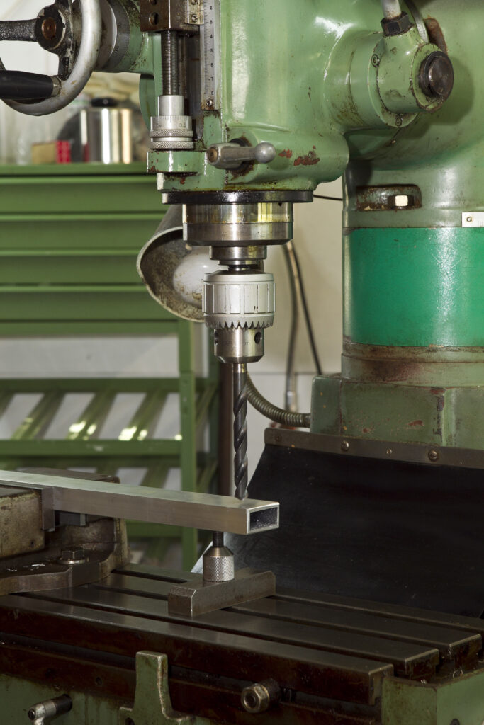
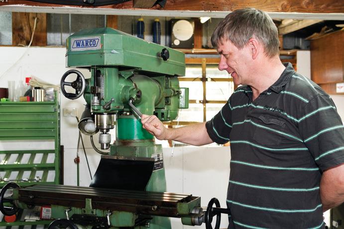
In a typical home engineering workshop progression, you buy a bench vise, some hand tools, and possibly a bench grinder. After you buy a small pillar drill then comes a big leap — buying a centre lathe.
Along the way you acquire more small tooling, drills, turning tools, etc. You make many useful items and produce a fair bit of scrap.
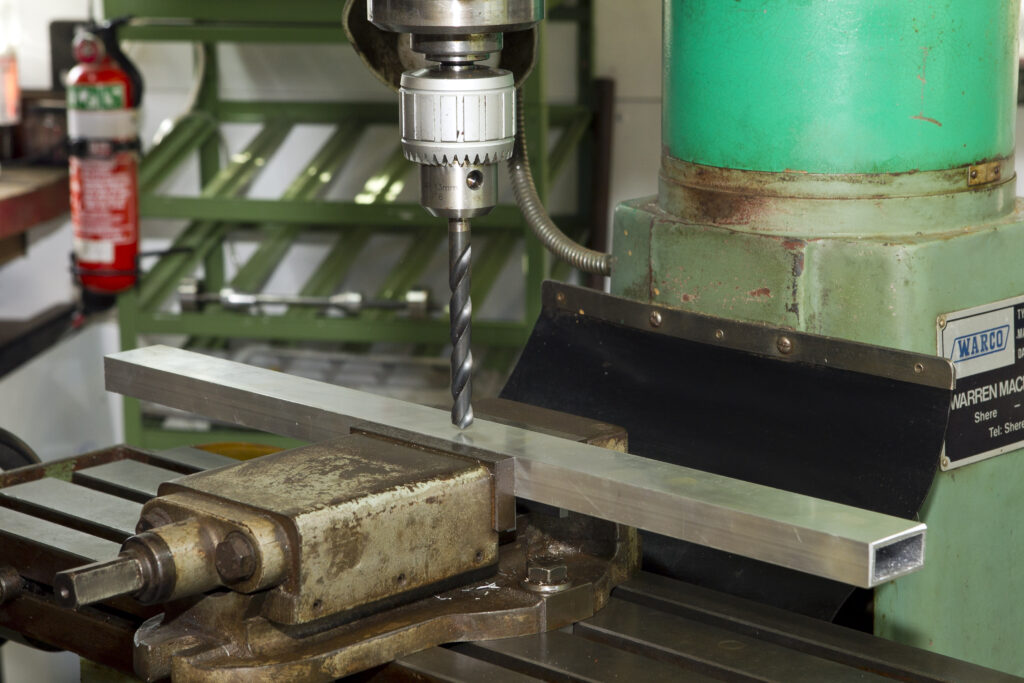
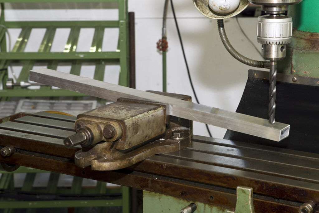
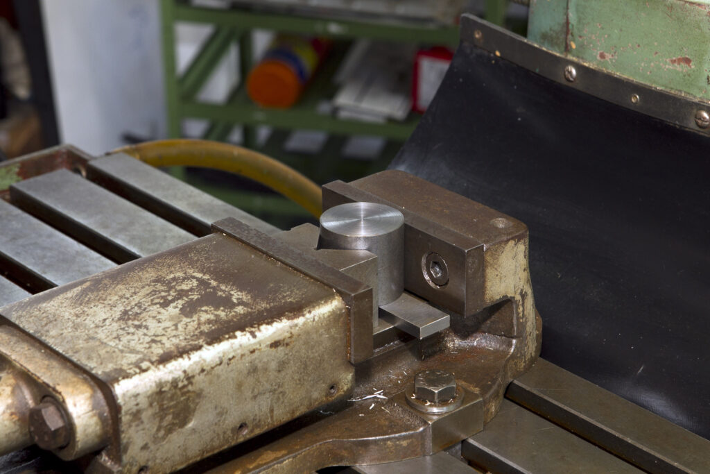
But then you find the lovely pieces you are turning out on your lathe require other features, especially holes more accurately positioned than you can mark out and drill on your pillar drill. As good as you have become with a file, that flat section needed on the shaft really needs to be machined. And how are you going to make a slot for that keyway?

Milling Part 3, cutting, clogging, and cleaning

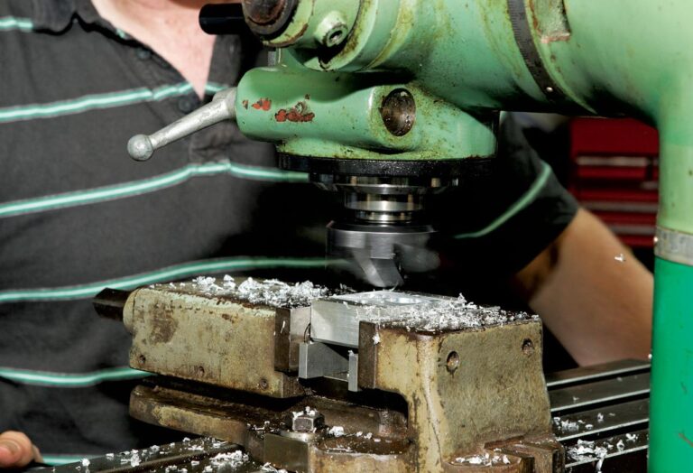
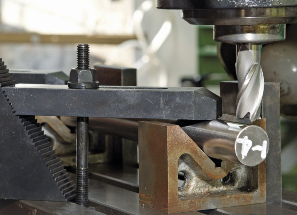
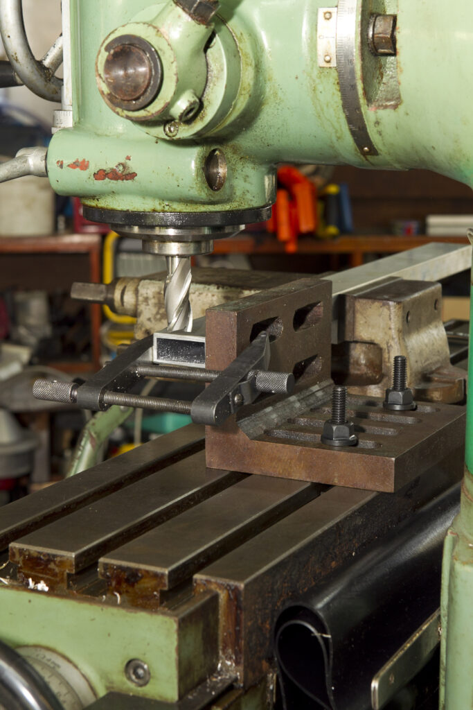
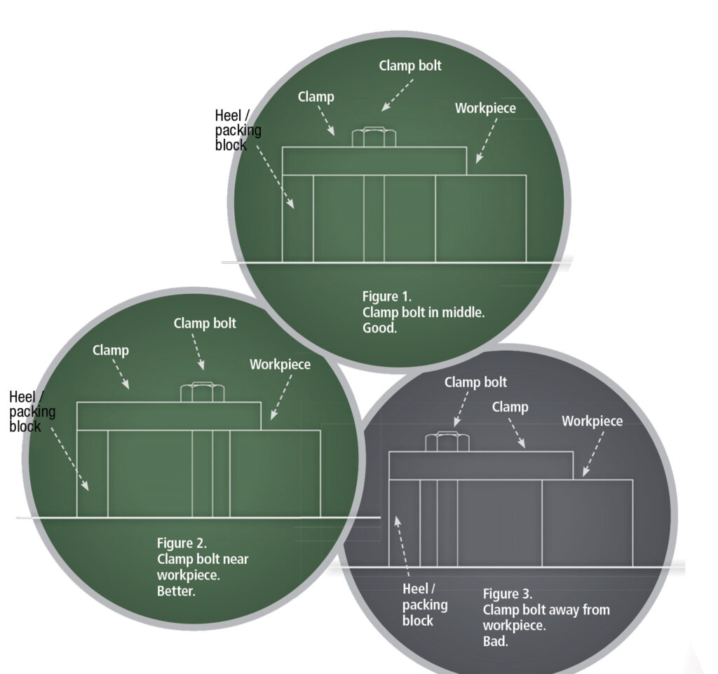
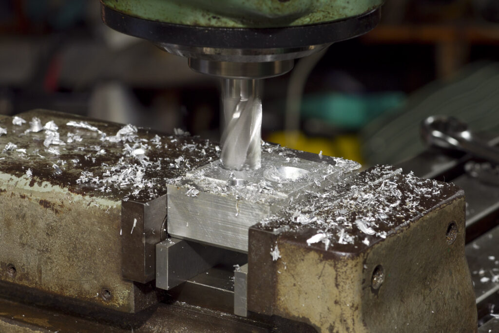
Once your component is securely clamped (see “Showing restraint” Part 2, www.the-shed.nz), ensure the cutting tool is held correctly in its chuck or collet holder, keeping tool overhang or stick-out to a minimum. Being rigid and stable applies as much to tooling as it does to the workpiece. Drill chucks are NOT designed to take side loads induced by milling and are exclusively for drills. Milling cutters should be held in a collet chuck or other suitable holder.