In this Part 3 and the final of our milling series, we examine removing material — which cutters and what material?
By Peter Woodford
Photographs: Geoff Osborne
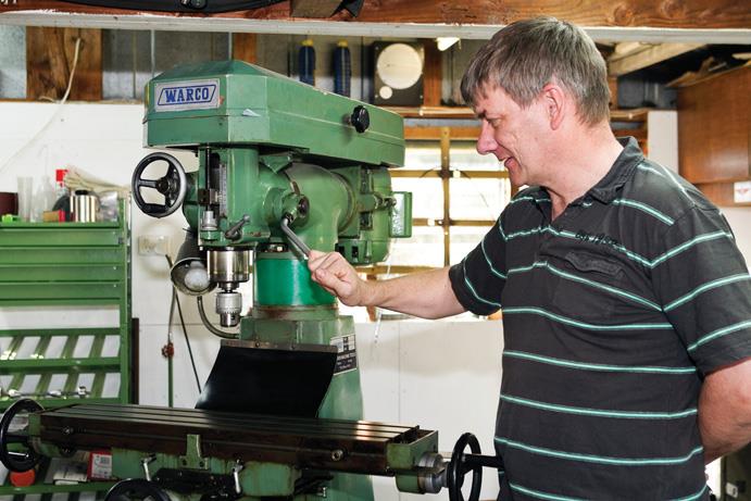
Once your component is securely clamped (see “Showing restraint” Part 2, www.the-shed.nz), ensure the cutting tool is held correctly in its chuck or collet holder, keeping tool overhang or stick-out to a minimum. Being rigid and stable applies as much to tooling as it does to the workpiece. Drill chucks are NOT designed to take side loads induced by milling and are exclusively for drills. Milling cutters should be held in a collet chuck or other suitable holder.
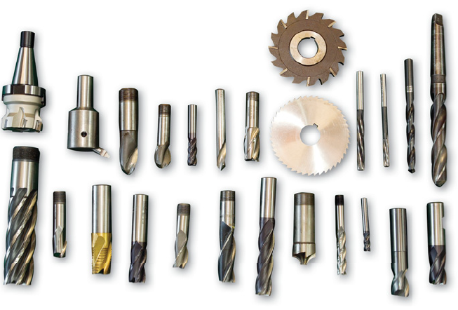
Cutting tools
There are three kinds of materials from which the most common cutting tools are made for the home workshop: high carbon steel, high-speed steel, and tungsten carbide.
High carbon steel (HCS)
As the name suggests, cutting tools made of this steel have a high carbon content, typically between a minimum of 0.8 percent and a maximum of 1.2 percent. This amount of carbon allows heat treatment to give a sufficient degree of hardness which will produce a good cutting edge. It means cutting tools can be produced from gauge plate or silver steel and then hardened and suitably tempered. Typically cheaper drill sets are made with high carbon steel.
Note that overheating of these tools will cause further tempering of the tool and a loss of hardness.
High-speed steel (HSS)
High-speed steel (HSS) is so-called because cutters made from this material could be run much faster than the carbon steel cutters prevailing before the development of HSS. For general use in the home workshop, high-speed steel is the most useful and cost-effective cutting tool material. The main alloy added to high-speed steel is tungsten. But HSS also has an amount of chromium, with smaller amounts of molybdenum, vanadium, and cobalt. The addition of tungsten alone does not provide the high temperature characteristics. A balance of all the ingredients allows for very high tool temperatures without the cutting edge losing any hardness. Typically high-speed steel drill sets are more expensive and end mills and slot drills will be made of high-speed steel. As with all things in life, you generally get what you pay for. High-speed steel cutting tools come in many grades and established brand names will be better quality than an unbranded cutter.
“Note that overheating of these tools will cause further tempering of the tool and a loss of hardness”
Spindle alignment
This is done with either a lever or plunger-type dial test indicator (DTI). This is mounted on a suitably rigid bar which needs to be a reasonable length, held in the machine spindle. The larger the sweep the more accurate the setting will be. The stylus of the DTI moves on a slip or parallel instead of measuring directly onto the bed of the machine. This means the stylus of the DTI will not be bouncing over the T slots as you sweep the spindle round. To check the X axis, sweep the spindle through 180°. Any change in the dial reading means your spindle head is not true to the bed. To adjust it, unclamp the head and move it until zero is achieved at both positions. Repeat this on the Y axis.
If the head of your machine is not clamped to allow adjustment or angle-setting, you may be able to shim the column to eliminate any error.
A small error will not be noticeable to the human eye but will become apparent when an assembly with accurately pitched-out holes for shafts for gears runs tighter than expected, or not at all. You can get a good indication that the spindle is true when fly cutting if, at the end of machining, the workpiece shows visible cross-hatching on the workpiece but this is not detectable by feel.

Tungsten carbide
Tungsten carbide cutting tools (also known generally just as carbide cutting tools) are made of solid tungsten carbide or, in larger cutters, replaceable tungsten carbide inserts with other trace elements, and sometimes a wear-resistant coating on the surface.
They are produced by a process called sintering where the tungsten carbide is used as a powder that is moulded under high pressure and temperature. Cobalt is included in the mix to help the particles “stick” together. These very hard cutters are able to deal with very hard materials and extremely high temperatures, although they are more likely to chip if not held rigidly.
Tungsten carbide comes in many different grades to suit the materials to be machined so the cost of keeping all the different grades makes this very expensive for the garage engineer. All cutting tools, no matter their shape, will have clearance angles and a cutting angle called rake or helix to shear (cut) the material being machined. This angle varies depending on the material being machined. In production machining, cutting tools specific for the material will be used. For garage engineers, general-purpose cutters and drills will get us by. If you are making hard work of it the next time you are drilling a hole, have a good look at the cutting edges and check that you have a clearance angle behind the cutting edge.
“As with all things in life, you generally get what you pay for”
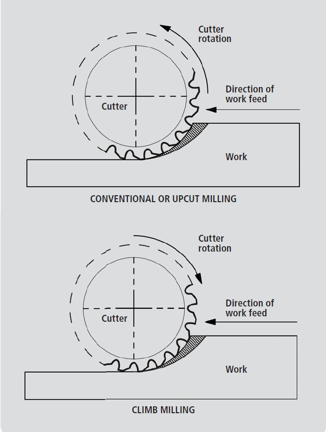
Upcut and climb milling
For efficient cutting, the cutting edge must arrive at the workpiece first. If not, it may still cut but excessive heat will be produced by the tool rubbing.
In up cut milling (or conventional milling) the tool starts at the bottom and cuts upward. The cutting edge rubs momentarily until it bites into the cut, which is no problem when the cutter is sharp. When the cutter dulls, the cutting edge rubs more. This becomes evident in the resulting poor surface finish.
In climb milling, the cutter is trying to climb over or along the workpiece. As the cutting edge takes a full cut straight away, there is no rubbing and a better surface finish results. The size of the swarf chip is the same by either method.
To get the benefits of climb milling you need higher spindle power and a very rigid set-up for your machine, component, and tool holding.
Unless your machine is fitted with ball screws or backlash eliminators, you will have to up cut mill. If you try to climb mill, the tool will continually grab the workpiece as it takes up the backlash in the machine lead screw as you feed the table. This results in a poor finish or damage to the workpiece and possibly chipping the cutting edges or breaking the cutting tool.
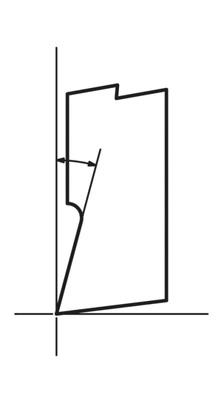
Rake angle
The rake angle of the cutting tool is often determined by the material being machined or the material the cutting tool is made from.
Positive rake is the most common of the rakes you will find. Most HCS and HSS drills will be positive rake, as will HSS and solid carbide end mills and slot drills.
Some materials machine well with a neutral rake — the most common in the home workshop is brass.
The widespread use of carbide tooling and the strength of carbide in compression make negative rake tooling within industry and its high material removal rates very desirable. Rigid machinery, tool holding, and high spindle power are required to get the best out of carbide tooling. A milling cutter with general-purpose carbide inserts can still be used in the garage workshop to take on hard or hardened materials. Just be aware it will be working your spindle bearings hard.
Negative-rake carbide tooling is very common in industry but its use in the home works is limited because of the higher power needed to drive negative-rake tooling and the rigidity required in the milling machine. Industrial cutting tools can also be made from Stellite, ceramics, and industrial diamonds, among other materials.
“If you continue, this will clog the cutter with possible damage to the workpiece and the cutter”
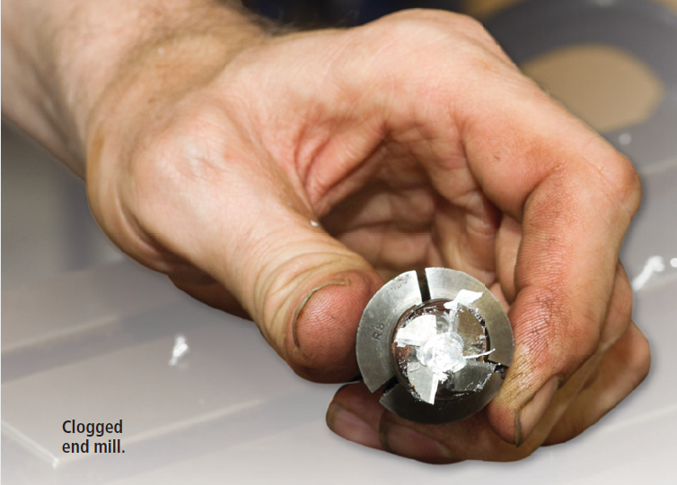
“A blunt cutter will have to be replaced but a clogged cutter may be cleaned and saved”
Cutting speed
Now a little bit of maths comes in when calculating the spindle speed for the drill or cutter. The spindle speed is dependent on both the material being machined and the cutting tool material. This is quoted in many engineering handbooks as surface speed in metres per minute (also written as metres/min or M/min), or in older publications as feet per minute. We will concentrate on metres per minute.
Academics do not like the use of the word “per”, but it is very common in the everyday language used here. Cutting speed is calculated as the distance the cutting edge of your cutter will travel in one minute. If you were to lay a strip of mild steel out that is 22 metres long and make a cut along with your cutting tool, taking one minute from end to end, you would have a cutting speed of 22 metres per minute. This is fine if you have a planer or shaper machine. But milling machines rotate the cutter so we have to use an equation to give us our spindle speed. With HSS being the most common cutting tool material in the home workshop we will concentrate on that.
Equation
By taking the figure for the material you are about to machine and putting this into a simple equation, we can find the spindle revolutions per minute (Rev/min)
The equation is 1000 x S
n x d
1000 = A constant (this converts S from metres to mm — this is because the cutting tool diameter is in mm).
S = The surface cutting speed quoted for a particular material in metres per minute (check which cutting tool material is being quoted).
n = equals 3.14 (to two decimal places will be fine).
d = diameter of the cutter or drill bit in mm.
You are going to drill a hole with a 20mm HSS drill or mill a slot with a 20mm HSS milling cutter. The process is not important. It’s the tool diameter and material that you are interested in entering into the equation.
A piece of mild steel is quoted as 22 metres per minute (HSS tool). So we have:
1000 x S = 1000 x 22 = 22000 = 350.3 revs per minute
nx d 3.14 x 20 62.8
Unless you have a machine with a variable-speed drive, the RPM figure you get at the end of the calculation may not be available. If this is the case I suggest you use the speed closest BELOW the one calculated. Running a bit slower is far better than running too fast and burning out your cutter.
As a suggestion, use the following cutting speeds using HSS cutting tools:
Metal M/min
Aluminum 60
Brass 50
Mild steel 22
Hard steels 12
Stainless 8
These figures are lower than you will find in engineering and tooling publications calculated for production output. They have been used by members of the Auckland Society of Model Engineers and give a very good tool life. Remember, as home garage engineers, we should value the life of a cutting tool (in effect, the cost to our wallet) as far more important than getting the job done a few minutes more quickly.
A simple rule of thumb for the garage engineer is
- For high carbon steel tools HALVE the speed;
- For tungsten carbide tools DOUBLE the speed.
This equation can also be used for turning, where d = the diameter of the workpiece being turned or the hole being bored. With the exception of when you drill on a lathe then d = the drill bit diameter.


Reamers
Drilling holes does not produce necessarily very accurate round holes. When drilling thin materials you have probably had a hole that looked tri-lobed. This becomes less noticeable in thicker material but closer inspection will show it may still be the case.
No problem when drilling a hole for a bolt but if you need an accurate-sized hole for a shaft to fit, using reamers is an option.
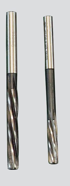
With reamers, drill undersize and then use the reamer to take out the remaining material to final size. Reamers split into two main groups:
- Hand reamers
- Machine reamers
Hand reamers have a slightly tapered lead-in to aid in aligning and starting the reamer and are driven using a tap wrench. They are not designed to be used on a machine. Machine reamers are parallel along their whole cutting length, are held in a drill or collet chuck, and are designed to be power-driven. Manufacturer’s data will give you the material allowance you should leave for reaming.
If you leave too much material it will clog the flutes, producing a poor finish and often an oversize hole and, in more extreme cases, break the reamer. The more common error when reaming is leaving too little material for the reamer to work with, often resulting in a poor finish. Reamers will follow a drilled hole so do not try to use a reamer to correct a slight positional error. For the reamer cutting speed, as a rule of thumb, you run reamers at half the speed of a drill of comparable size.
Reamers are like apprentices — give them too much to do and they will choke; give them too little and they will wander.
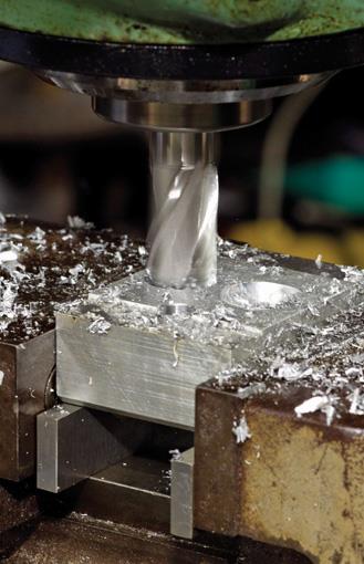
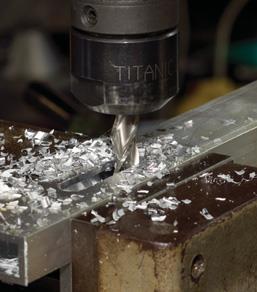
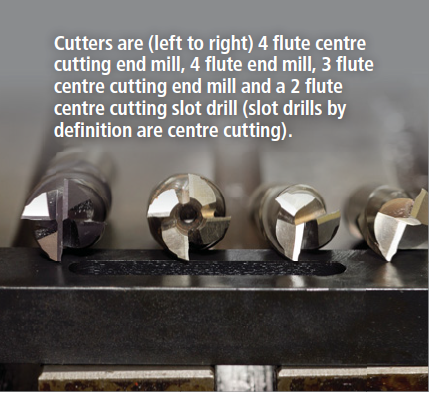
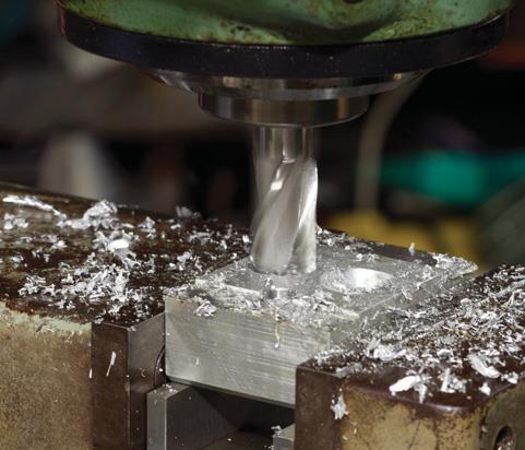
Milling a slot
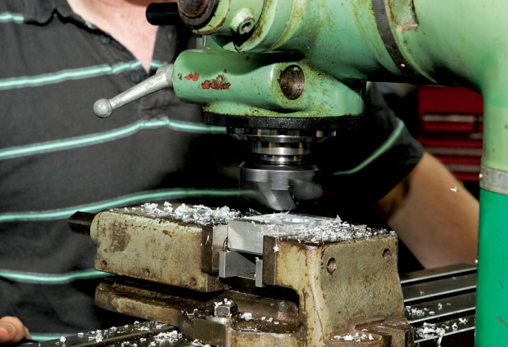
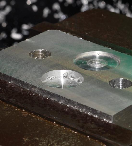
Milling a slot requires a centre cutting cutter as you plunge into the workpiece, otherwise, the material at the centre will not be cut but will tear. As it does, the resulting friction will cause rapid localised heating, melting the material. If you continue, this will clog the cutter with possible damage to the workpiece and the cutter.
The difference between a centre cutting cutter and an ordinary end mill plunged into an aluminum block will show in the contrast between a cleanly cut hole and the torn or deformed material at the centre of the second hole. If the machine begins to labour, or if the sound of the cutting changes tone for no obvious reason, stop and investigate the cutter which may have become blunt, or the flutes may be starting to clog.
A blunt cutter will have to be replaced but a clogged cutter may be cleaned and saved.
If you do not have a centre cutting cutter you could always drill the start of the slot and then continue with an end mill to finish. Save your expensive cutters for finishing work by using drills and fly cutters to do the roughing out work because they are easily re-sharpened.

A long slot
In the first article on milling (“Time for a milling machine?” Part One, www.the-shed.nz) I said when you plan the machine spot in the workshop, you need the space for table movements and the possibility of a workpiece overhanging the table. For me, it was a workpiece 8 metres long.
We were putting on deck roofing and I decided that, instead of fixing the beam supports for the cover directly to the house, it would be easier to be able to slide them into position inside a slotted piece of box section.
I had a piece of 25x50x3mm steel box section eight metres long. In it, I machined a 12mm-wide slot end to end. To do this, I clamped it to the bed of my milling machine against stops placed in the T slots. It was supported on rollers at each end of the machine. I machined, moved the material, machined, moved the material, etc. It took some time but the job was done, money saved, and I got great satisfaction.
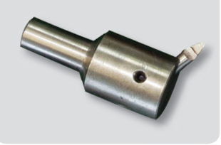
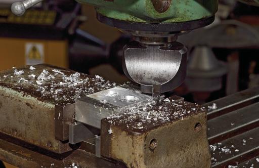
Fly cutter
Fly cutters produce good, flat surfaces in one pass — assuming that your machine is set true. Every garage machinist should have several different-sized fly cutters. Typically a single-point cutter uses a high-speed steel (HSS) or a carbide tool bit.
When using a large diameter cutter or a fly cutter, if there is a noticeable back-cut as the cutter passes over the workpiece being machined, the spindle is probably out of true.
The depth of cut for a fly cutter will be small compared to other cutting tools so material removal will be slower, but the advantages far outweigh this drawback. Using fly cutters will allow you to keep your expensive cutters for finishing work rather than general material removal. You can grind a form on the cutting edge of, say, a particular radius, then machine this radius into the workpiece.
One of the greatest advantages of fly cutters is the ease with which they can be re-sharpened on any off-hand grinder, unlike end mills and slot drills which have to go off for specialist re-sharpening.
When you are calculating the speeds for fly cutters, the diameter that the cutting edge sweeps should be used in the spindle speed equation.
DANGER: When you are using your milling machine for fly cutting, only the body of the fly cutter may be visible at speed and the actual cutting edge which is further out may become invisible to the eye. KEEP YOUR FINGERS WELL AWAY.