Part One in a three-part series on the milling machine for your workshop
By Peter Woodford
Photographs: Geoff Osborne
In a typical home engineering workshop progression, you buy a bench vise, some hand tools, and possibly a bench grinder. After you buy a small pillar drill then comes a big leap — buying a centre lathe.
Along the way you acquire more small tooling, drills, turning tools, etc. You make many useful items and produce a fair bit of scrap.
But then you find the lovely pieces you are turning out on your lathe require other features, especially holes more accurately positioned than you can mark out and drill on your pillar drill. As good as you have become with a file, that flat section needed on the shaft really needs to be machined. And how are you going to make a slot for that keyway?
“So, once you have made the case for buying a vertical milling machine, new or secondhand, what you should be looking for?”
Milling machine
Another even bigger leap is now required — a milling machine. With this, you will be able to accurately pitch out holes, machine flat, machine slots, machine angles, square-up edges, and maybe start that model steam loco you promised yourself.
This leap often seems to be very daunting and it actually may be, in part due to the different milling machine types. All centre lathes are basically the same layout and just vary in size. The main configuration of milling machines is split into two basic groups: horizontal and vertical (referring to how the spindle of the machine is mounted), with a few that are both.
In the first article of our introduction to milling, we will look at the most useful type for the home workshop: the vertical milling machine. So, once you have made the case for buying a vertical milling machine, new or secondhand, what you should be looking for?
Size
Whatever you plan to make, don’t forget that when friends find out about your purchase, they will always have car and boat parts for repair or modification. So, unless you are going to be a clockmaker, you may want a machine big enough to cope with some of the typical sizes of car or boat parts. No matter what size machine you buy, you can be sure that the first jobs you are asked to do will be too big for your new purchase.
But, unless you have lots of space and money, don’t get carried away with size. When you have a typically small job to do, a very large machine can be very ungainly to use. The working footprint of a milling machine is also generally larger than its base size, so don’t forget when you plan the machine spot in the workshop, you need to allow space for table movements, and the possibility of a workpiece overhanging the table.
“When you have a typically small job to do, a very large machine can be very ungainly to use”
Power
Do you have single or 3-phase power available? Single phase makes things easier as you can plug in and go. But check the current required as a 10-amp supply may not be suitable and you may need to upgrade the wiring. If you have three-phase, this will open up your options with the possibility of using ex-industrial equipment.
You get better starting torque from 3-phase than from single-phase and 3-phase is much easier to run in reverse. This is very useful in some processes, for example, reversing the spindle to wind out a tap if you have been tapping under power.
Converting ex-industrial equipment to single-phase motors is not always an option due to space limitations, as single-phase motors are usually larger than their 3-phase equivalent. But the use of a single-to-3-phase converter may be an option as most smaller machines tend to be single-phase. If you buy new, you may be able to choose single or 3-phase.
New or second-hand?
Is the well-used Bridgeport mill at that price as good as a new, imported machine with a warranty?
There are some very good second-hand machines out there, but worn-out is worn-out, no matter what the name on the side.The latest machines coming out of Asia are now well worth considering. You may also be able also to do a deal on a starting tooling package with your new machine. When looking at a machine, be it new or second-hand, find yourself a friendly toolmaker, miller, or model engineer to help you assess the suitability of your prospective purchase.
Axis size — the Z factor
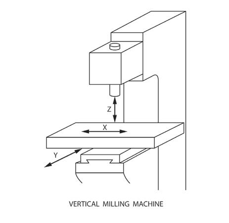
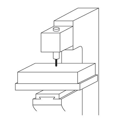
The axis of movement lengthways (X), sideways (Y), and up-and-down (Z) — the X Y Z sizes — will be quoted as the capacity of the machine. To overcome the limitations of the X axis moving in a plane in one direction, and the Y axis moving in a plane at right angles, you can always reposition the workpiece on the table and drill or machine in several operations. A little inconvenient, but possible.
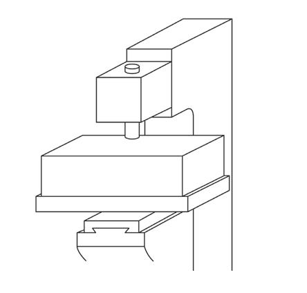
But with the Z axis, don’t forget you have to allow for the combined height of the tool holder or drill chuck, plus the tool held over the table. This can greatly reduce the maximum height on the table of the component you can drill or machine. When buying a milling machine, pay close attention to the dimension of the Z axis. You could possibly gain more Z height with a riser block fitted into the pillar, but this is not possible with all machine designs.
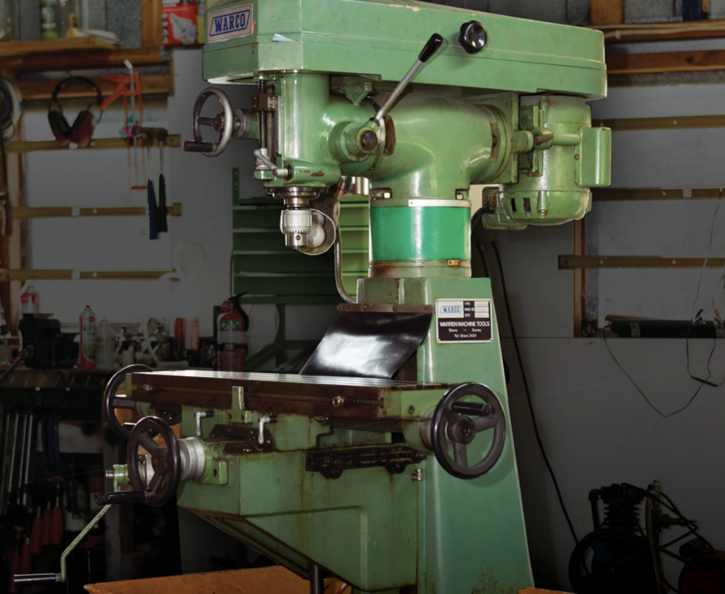
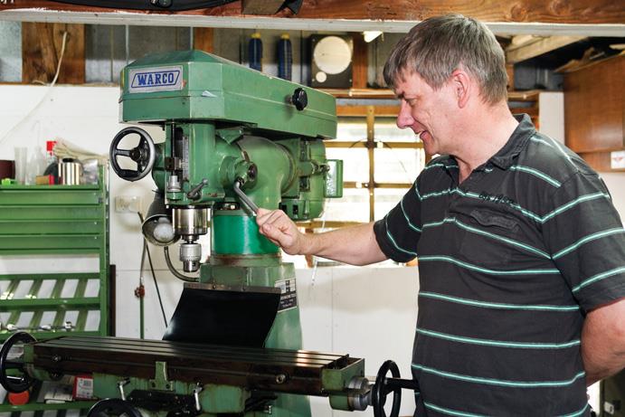
I have inserted a riser block in my machine (see bright green section) which is a Warco milling machine with a bed that is 760x180mm, and axis movement maximums of:
X – 560mm;
Y – 200mm; and
Z – 440mm, bed to spindle, which includes the 100mm riser block added.
“The Morse taper is common on smaller machines and mill/drills, especially in New Zealand, and is good for drilling”
Spindle taper types
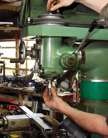
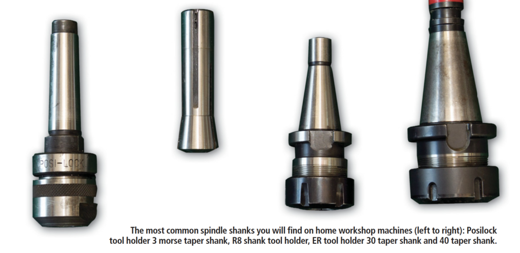
A spindle taper is the way the tool holder is held in the machine, with the spindle usually held in place by a drawbar. There are several common types of spindle taper.
The Morse taper is common on smaller machines and mill/drills, especially in New Zealand, and is good for drilling. But this type of holding taper is not preferred for milling. The Morse taper is not designed for the side loading that occurs when milling.
The R8 taper is also a common taper found on small to medium-sized machines, is relatively cheap, and designed with milling in mind. It has the advantage that the tool is held very close to the spindle nose, increasing rigidity and saving important height in the Z axis.
The 30, 40 and 50 series tapers are the most common industry-standard tapers. The bigger the number, the larger the holder, so you are most likely to find 30 or 40 series tapers in the small/medium-sized machines. Very small machines may have other, less common spindle tapers.
These R8, and 30 and 40 series tapers are preferred for milling. All R8 tapers have a common drawbar thread — 7/16 UNF — but 30 and 40 series tapers do vary, with manual machine and CNC machine types having different drawbar threads. Check carefully as differences are not immediately obvious to the untrained eye.
Quill
Most vertical milling machines of the size suitable for the home engineer will have a quill-type spindle, ideal for drilling holes, boring holes, reaming, and assisting in setting a workpiece. This quill is operated by a lever driving a rack and pinion. It may have a fine feed option using a hand-turned wheel and is sometimes gear driven from the spindle.
Tooling
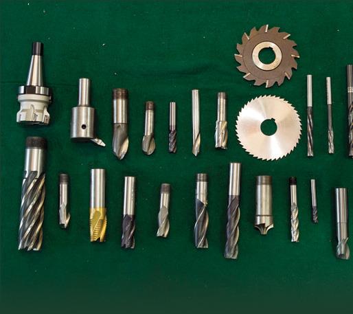
The tooling package you need can be very daunting. It is possible to spend as much money as you have just paid for your machine (or more) on tool holders, cutters, and component-holding equipment (vises, clamp sets). A second-hand machine may already have an assortment of tooling. You will need a basic set of tooling to get you started and the rest can be built up over time.
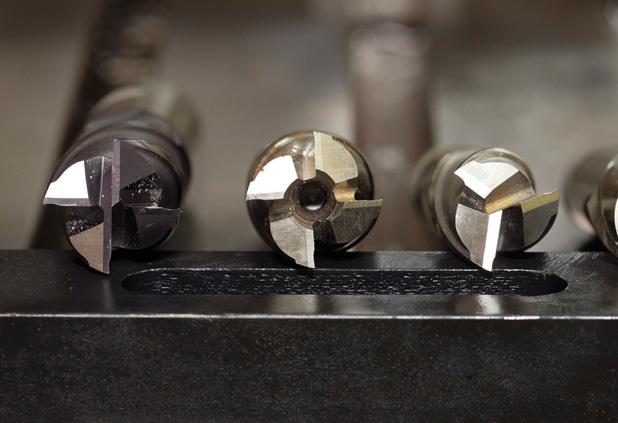
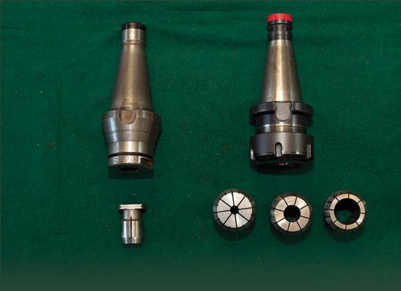
With tool holding, the R8 system holds the tooling directly and comes in metric and imperial sizes. These are relatively cheap but several will be needed to cover the different tool sizes to be held. Collet chucks are available for the R8 series but this reduces Z height. The 30 and 40 tapers have collet chucks of different types, including Autolock and the now more-common ER series of collet chucks.
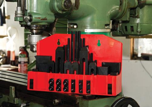
Tee-nut clamping sets consist of varying lengths of studs, tee-nuts, nuts, connector-nuts, finger-clamps, and stepped heel-blocks, usually in a purpose-designed holder.
Starter milling packages are often available from tool suppliers and if a new machine does not come with one, ask what deal they might do. A typical package might include a machine vise, tee-slot clamping set, tool holder and collets, and a face mill.
“It is possible to spend as much money as you have just paid for your machine (or more) on tool holders, cutters, etc”
Machine vises
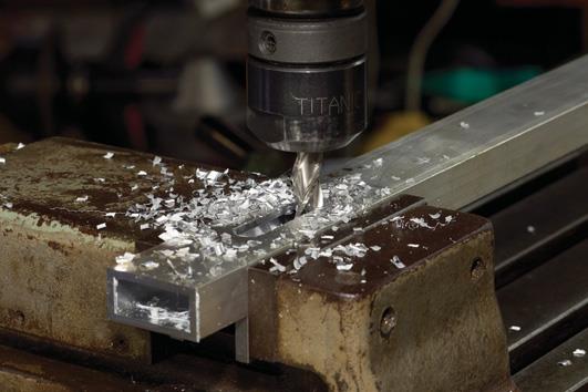
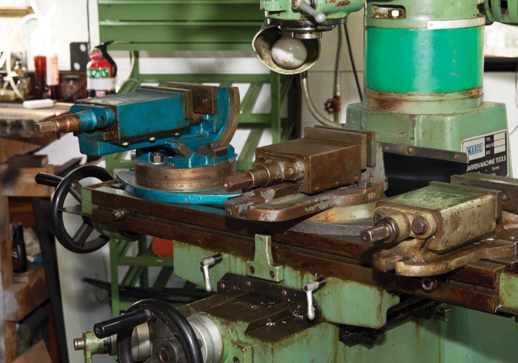
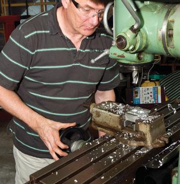
A machine vise is a must. That vise you use on your drill press is probably not going to be suitable for holding a component to be milled as the side-loading pressure will need to be contained in a solid machine vise. These come in many sizes, often available with a swivel base to allow angle-setting for machining.
A swivel base will steal some of your Z height, so check that the vise can be removed from the base and used without it if necessary. If you were to have one machine vise, the type with a removal swivel base offers you both basic and angle-setting options. However, a tilting-and-swivel-base vise cannot usually be removed from its base and used as a simple vise, so does not have that variety.
Belt or gear-driven?
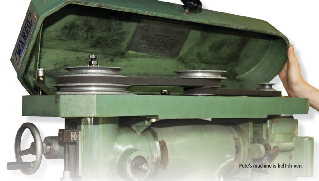
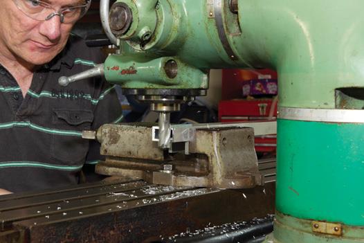
You may not have a choice whether you get a belt-driven or gear-driven spindle. A gear-driven option is a positive drive that will probably have a larger number of speeds available but will be noisier than belt. The quieter belt-drive may be an advantage, depending where your machine will operate. If you jam the spindle, the belt-drive may slip and save more serious damage. Stripping the gears is painful and expensive.
A variable speed drive works either through expanding or contracting pulleys. Motor-speed control also gives full variable spindle-speed within a set range.
If you have a direct-drive, motor-speed control, check that there is enough spindle torque at slow speeds. Milling machines are often very compromised at slow speed, making it easy to stall the spindle when you are using larger drills or cutters.
Digital readout (DRO)
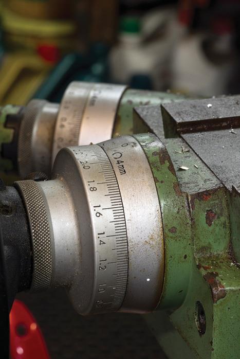
It’s great if your milling machine comes with a digital readout (DRO). If not, or your budget can’t stretch to this option, check whether the machine can be easily retro-fitted. Once you have used digital readout on a machine you will wonder how you ever got by without it.
Looking at a clear digital readout rather than battered, engraved marks on the handwheel has many advantages when you are setting up, pitching out holes, moving longer distances, or having to count how many turns of the handwheel to get to next position.
Power feed
Power feed is not absolutely necessary for the home engineer as we do not have production pressures on us. The smaller machines are unlikely to have power feed, but bigger machines might have a power feed on the X axis. If not, check if a power feed could be retro-fitted as this may prove desirable as your ability improves and funds become available.
“Once you have used digital readout on a machine you will wonder how you ever got by without it”
Tilting machine head
A tilting machine head will allow you to machine a feature on an angle, or drill a hole into the angled face of a component. It’s very useful if the component cannot be held at the required angle.
But look at how rigid the machine is and how well the head is clamped in position. Every tilt option can reduce the rigidity of the machine. The more rigid and solid your machine and the better you clamp your workpiece (without distorting or damaging it), the less chance of the dreaded cutter-chatter when you are machining.
Mill/drills
The round column mill/drills should really be called drill/mills. These make good drilling machines but are very compromised mills. There is some great work being produced on some of these machines and several members of the Auckland Society of Model Engineers (ASME) have mill/drills producing first-class components.
But I feel, as mills, these machine have several big drawbacks.
Most have a 3 morse taper spindle held in place with a drawbar. The morse taper was never designed for the side loads induced during milling, so only light milling should be attempted.
The quill has to be lowered to move the cutting tool down to take a cut. This increases the overhang of the spindle from the machine’s head, reducing rigidity and increasing the likelihood of chatter. When you are cutting, this will get worse the further the quill is extended from the head of the machine.
Probably the biggest flaw is the round column. There is a problem if you have to move the head up for more clearance in the Z axis, or down to reduce the quill overhang and increase rigidity to stop the chatter of the cutter. As soon as you loosen the head to move up or down, you will also lose position in your X and Y axis as it will move around the column, even if only slightly. This will mean you have to some way to find your position accurately on the workpiece.
I have seen many different ways to overcome this problem, including a laser bounced off a mirror across the workshop and back to a point on the machine-head to aid accurate repositioning, or stop-blocks attached to the column.
My recommendation is unless one falls in your lap or is very cheap, be warned: you will probably end up very frustrated with it and will give up on milling (hopefully not), or will have to try to sell it on to someone — at a much reduced price if they have read this article. There are some dovetail column mill/drills on the market now but for some reason they seem to be only available with 3 morse taper spindles. This is a shame as a R8 or 30 series taper would make these worthy of serious consideration.
“All machines must be mounted on a substantial base“
Level
Your new (or secondhand) milling machine is purchased, delivered, and positioned in your workshop. All machines must be mounted on a substantial base. Now, do not waste any time but level the machine as soon as possible, even if it is with a builder’s spirit level (engineers call these approximate). Make sure all the milling machine’s levelling feet are loaded with the weight of the machine.
The machine is a big lump of iron but, even so, there is an engineering term called “creep”, meaning all engineering materials will move over time if a load is applied.
If you do not ensure all the feet are carrying the load of the machine, you are effectively applying an uneven load that over time will distort your machine. The bigger and more solid the machine, the longer it will take, but it will distort. Then at a convenient time, find a friendly engineer who will lend you an engineer’s level to level the machine — accurately.
See Part two: Clamping your work.

