The Shed Logo
Search
Close this search box.

Rolling stool build

My wife, Rosaleen, loves to cook, and will happily spend an afternoon in the kitchen cooking meals to be frozen and given to our daughters and their friends whenever the need arises or opportunity presents. However, arthritis makes standing in one position for long periods difficult for her. She wanted a stool for the kitchen, but ours is a galley-style layout and quite narrow. It’s wide enough for one person to walk past another working in the space, but the presence of a stool would present a major obstacle. “Why don’t you invent something?” she said. I love a challenge like that.

A unique design challenge leads to a pleasing three-legged rolling stool prototype
By Hugh McCarroll
Photographs: Hugh McCarroll

My wife, Rosaleen, loves to cook, and will happily spend an afternoon in the kitchen cooking meals to be frozen and given to our daughters and their friends whenever the need arises or opportunity presents. 
However, arthritis makes standing in one position for long periods difficult for her. She wanted a stool for the kitchen, but ours is a galley-style layout and quite narrow. It’s wide enough for one person to walk past another working in the space, but the presence of a stool would present a major obstacle. “Why don’t you invent something?” she said. 
I love a challenge like that.

Setting up the diagonal supports which hold the vertical tube in position
Original configuration with two support legs at 45 degrees

Parts list

Undercarriage
2 wheels 70mm dia x 23mm wide at hub
25x25x1.6mmL al 425mm long
30x3mm strip al 425mm long

Base assembly
Vertical: 25x25x1.6mm sq al tube 500mm long
Diagonals: 25×21.6mm sq al tube ex 470mm long (2 req)
Top connector: 30x3mm al strip ex 100mm long
Support leg: 10mm dia steel rod 470mm long
Support leg attach bracket: ex 40x40x3mm al L 40mm long (2 req)
Horizontal seat support: 20x20x1.3mm sq al tube 280mm long
Step: ex 280x165mm MDF
Hinges: 50x15mm steel or brass (2 req)
Step support seat: ex steel scrap 3mm thick.

Seat assembly
Seat: ex 240x180mm MDF
Seat supports: ex 25x25x1.6mm al L 220mm long (2 req)
Vertical: 20x20x1.6mm sq al tube 600mm long
Brace: ex 4mm dia fence wire 400mm long

Exciting design stage
A regular stool would be too bulky. There is already a small plastic step she uses to reach the high cupboards which I step over if I want to get past her to the far end of the kitchen. I thought of a shooting stick – a walking stick with a folding top that folds out to form a small seat. You can sit on it, balancing with legs apart, but taking some of the weight off your feet. The idea grew from that.
A wheeled base like an inverted Tee would be better, more stable than a shooting stick, and with two wheels so you can roll sideways while still sitting on it. Perhaps a third leg to make it like a three-legged stool. You could push back with your feet to lift the third leg off the ground and slide sideways a metre or two to get something out of reach. The more the idea developed, the more I liked it.
So I developed a concept on Sketchup over a couple of evenings. It looked very promising – easily folded away when not in use, with two swinging support legs which fold out, and a fold-down step to lock the supports in place. This would be very stable and could also replace the step she currently uses.

I heated the support legs with a gas torch and bent them round a jig
The step sits on a bracket brazed to the support leg (final configuration)

Tools required
Lathe (if wheel bushes required)
Brazing gear
Pop riveter
Drill and hand tools

Aluminium the answer
I started making the prototype out of timber, but it was clearly going to be too heavy and bulky. I abandoned that approach and redesigned it to be made of aluminium extrusions, which looked much more promising.
Aluminium is such an easy material to use. I have a large supply from many years of buying it in 5m lengths and never throwing off-cuts away. A 25x25x1.6mm square tube, with a 20x 20×1.6mm square tube inside (to allow height adjustment) was the choice for the base and seat support.
I bought a couple of cheap plastic wheels, 70mm dia x 23mm wide hub, and a 10mm diameter bore. First up I turned two aluminium sleeves 10ODx6IDx25mm long from some bar stock. This allowed me to use 6mm diameter bolts, of which I also have a large selection.
I envisioned a bicycle-type seat on a pole and an undercarriage with two wheels, like an inverted Tee on wheels.
The undercarriage bolts at right angles to the main vertical tube at the bottom, with a piece of flat bar 25x3mm on one side and 25x25x1.6mmL section on the other. The wheels are bolted between these 400mm apart. The vertical tube is held square by two more 25mm square tube diagonals. These are pop riveted to the undercarriage at the bottom ends and to each other at the top using pieces of 25x3mm and 25x25mmL (similar to the undercarriage, but shorter). The inside of the vertical tube needs to be clean so the inner tube can slide up and down for height adjustment.
I made two folding supports out of 10mm dia round steel bar, which I heated and bent round a jig. I brazed a washer in place at the top and drilled a 3mm dia hole at the bottom. The two supports fit between the angle sections top and bottom, while the brazed washer bears against the top angle section. A 3mm dia transverse bolt secures the bottom end.

Centre punching the inner square tube...
...and drilling the holes that allow height adjustment

Three legs
The problems came with the fold-down step that secures the folding supports in place. The geometry is tricky and I couldn’t visualise all the angles. I had in mind that the step would be hinged to the diagonal tubes and fold down when it is stowed away. When the supports are folded out 90o it would swing up and the supports rotated to 45o. The step would then fold down and lock them in place. I tried several different ways of attaching the folding step and shaping the step, but nothing made it work. Then I realised I didn’t need two folding supports – one at 90o would be sufficient and simpler.
So I replaced the piece of 25x25mmL section at the top with a new one with a single 10mm dia hole centrally, and drilled another 3mm dia hole centrally in the undercarriage L section.
With just the one support arm, it becomes a three-legged stool. The fold-down step continued to taunt me with its geometry. Everything is interrelated. If you make it deeper, that affects the attachment point and the height of the step. If you make it wider, it affects the support leg movement. I had made four steps before I figured all the limits and constraints. It was obvious afterwards, but hindsight is always 20/20.
And the final step was too small to realistically function as a step.

Checking the two support legs (origianl configuration)
I modified the step size and shape several times
The step support bracket taking shape
The finished saddle and spring clip that secures it at a comfortable angle
Vice grips hold the step support bracket in the correct position so the step will be level when in use

Eureka moment
This irritated me and I thought about ways to have the rolling stool and a wider fold-down-step. Then the ‘Eureka’ moment: the support leg does not need to be attached at the bottom. Making it a straight length hinged at the top would allow it to be swung out when folding out the step. What is required is a locking system to secure the support leg to the step in the functioning position. Not what I originally set out to make, but a better design in the end. This is the enjoyment of making stuff and developing an idea – you improve the design as you go. By now the stool had gone through at least four iterations.
The new step can be as wide and as deep as I want. I settled on 280mm wide by 140mm deep, a semicircle big enough for a foot to stand securely.
The step sits horizontally on a seat brazed to the support leg. The seat has an upturn at the end which locks in place in the bottom of the step so it cannot slide out when weight is applied. The step locks the support leg in place so the stool is very solid and stable.

The step support bracket brazed in the right place at the correct angle...
...so the turned up end fits neatly between two steel strips screwed to the underside of the step
I turned two bushes to fit the bore of the wheels
The bushes hold the undercarriage side members 25mm apart and allow the wheels to turn freely

Prototype done
The step and the saddle are from MDF off-cuts. The saddle has two lengths of 25x25x1.6mm L section screwed to its underside with a 6mm dia bolt securing it to the 20x20mm square tube that fits into the base. The other attach point to hold the saddle at a comfortable angle for sitting on is a length of folded 4mm wire (good old No 8 wire) to form a spring clip. Several holes in the 20mm square tube allow the saddle to be secured at different angles.
The height of the saddle can be changed, with a number of 6mm dia holes in the 20x20mm square tube and a single through hole in the base and a 6mm dia bolt.
The saddle can rotate flat for storage so the whole thing folds to a 50mm thick flat pack. I was quite pleased with it.
The step works well too. You can stand on the step with both feet and the saddle between your knees so you are quite stable.
However, Rosaleen asked for a more comfortable saddle and I realised it also needed a little wheel at the end of the support leg so it won’t scratch the kitchen floor. So I made the executive decision to keep this stool for my use in the shed and make another for her.
It works as I hoped, weighs 2.5kg and folds flat so it can be kept handy for use whenever needed.
Having made the prototype I’ll make a number of other changes to the design to incorporate a better saddle, and add a little wheel on the bottom of the support leg so the stool can roll sideways without having to push it back, just sidle sideways like a crab! That will be her Christmas present.

It works pretty well. Moving sideways is quick and easy

Easy Imperial
I remember the old pre-decimal days and the nesting tubes with 1/16 inch wall thickness and ⅛ inch size increments. Everything nested easily, ¾ inch nested in ⅞ inch which in turn nested in 1 inch tube and so on. It doesn’t work as well with decimals. Looking back it’s about the only advantage I can think of where the imperial measure system is better than the metric system.

Share:

More Posts

How to steam bend wood

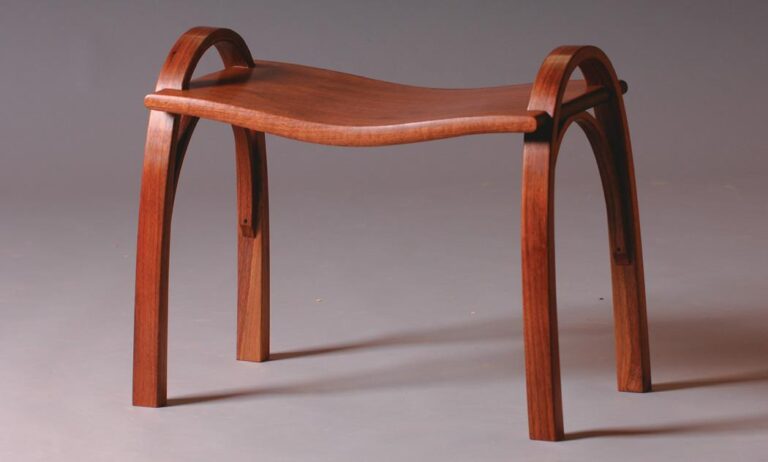
This project to make a stool was developed as a way of introducing students to a number of basic
wood-bending and shaping techniques, whilst also giving experience in several useful applications of the router.
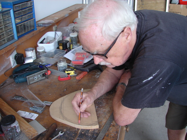
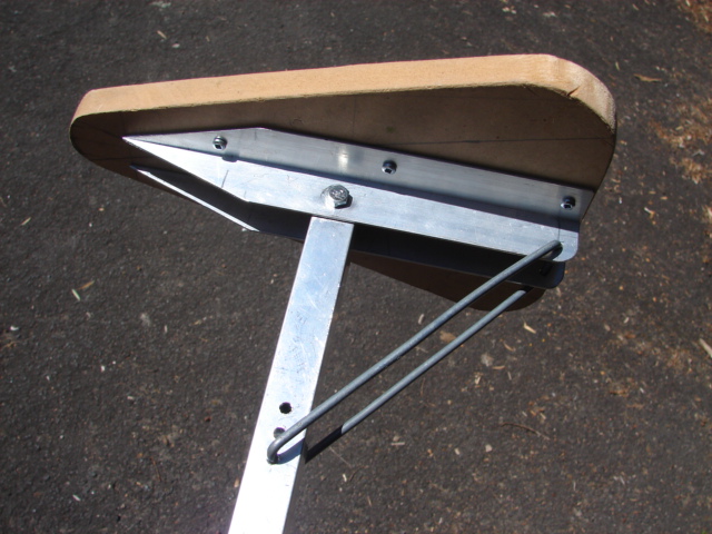
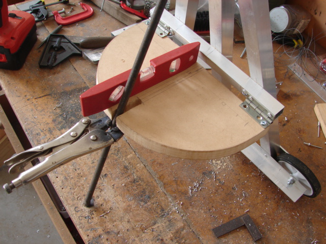
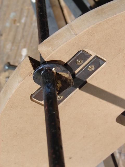
The stool consists of two legs in the form of continuous steam-bent hoops or arches, which are housed into matching radiused slots at either end of a curved seat. The legs are stiffened by the addition of smaller arches that fit between them and the centre underside of the seat. For the purposes of this article, I am going to focus on the steam-bending aspect involving the legs as that is the technique that woodworkers seem the most reluctant to try.