Making a bar stool is a learning curve for a TIG welding novice
By Jude Woodside
Photography: Adam Croy
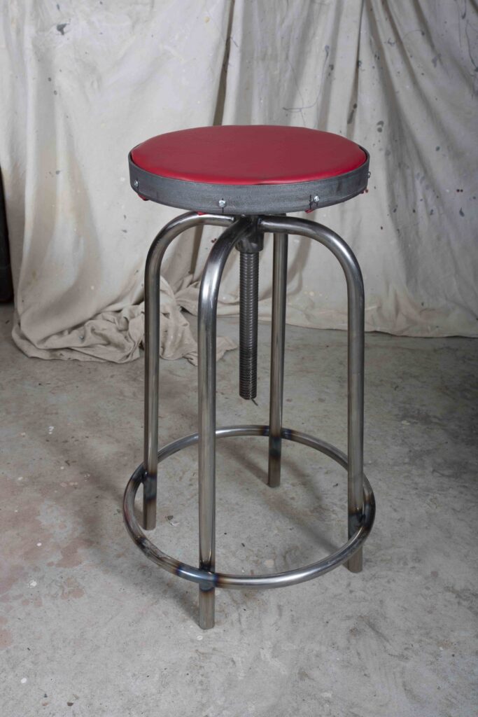
I have wanted to make an elevating bar stool for some time. They are a relatively simple design – four legs attached to a nut through which an acme thread runs, raising and lowering the seat.
However, attaching the legs to the nut is problematic. The nut is usually a fairly large piece of steel, in this case it’s 38mm diameter, and even with the hole and threads cut it still has a wall thickness of nearly 10mm. The legs on the other hand have a wall thickness of only 2mm. That size differential makes using MIG welding difficult. It can be done of course but it isn’t quite as straightforward as usual.
I felt it was ideally suited to TIG welding and as I hadn’t tried TIG before I thought this might be a good opportunity to get some experience.
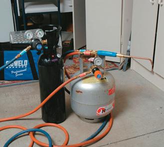
TIG welding uses a tungsten electrode to create an arc that melts the metal. A filler wire is used to add metal to the weld as in the old-school gas welding. TIG requires pure argon so it meant getting a new gas bottle and a TIG torch.
Sourcing the parts
The screw is usually either an acme pattern or the metric equivalent, or a trapezoidal thread as in a lead screw. I could have cut one on the lathe and it occurred to me to do so but as always I was constrained by time and these screws and nuts are readily available. In my case I sourced one from Nuweld in Papakura who manufacture G-type welding clamps. It’s about the ideal size at 300mm long and 20mm diameter and came with a 38mm round nut.
I decided the legs needed to be 22mm tube and I managed to source some off-cut pieces of 22.2mm furniture tube from a manufacturer. This tube, as noted, has a 2mm wall thickness and that introduced the next issue.
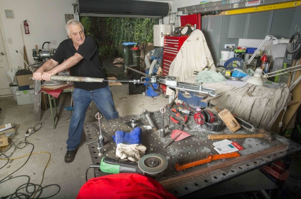
There are many tube benders on the market, mostly used by plumbers for light copper tube and I briefly flirted with the idea of buying a cheap Chinese one. However I was warned that it probably wouldn’t cope with the 22mm x 2mm wall tube and the formers might shatter. That left just one option – the Bramley Tube Bender. This venerable piece of equipment is made in New Zealand so it’s not cheap, but it is the best and most cost effective means of bending this grade of furniture tube. In fact it will do two larger sizes of tube and comes with five formers for different diameter tube. The bender certainly gives you some confidence that it will do the job – it’s very solid and clearly engineered to last.
The tube bender can be used after fitting it in a vise or you can purchase a floor-standing unit to anchor it to the floor. In my case, I used the vise on my heavy welding bench but I was still forced to create an extension handle because the bender caused my bench to slide all round the floor. It requires two people to lift usually. The extension for the handle allowed me to apply more force to the bender so it didn’t just move the bench across the floor.
Issue solving
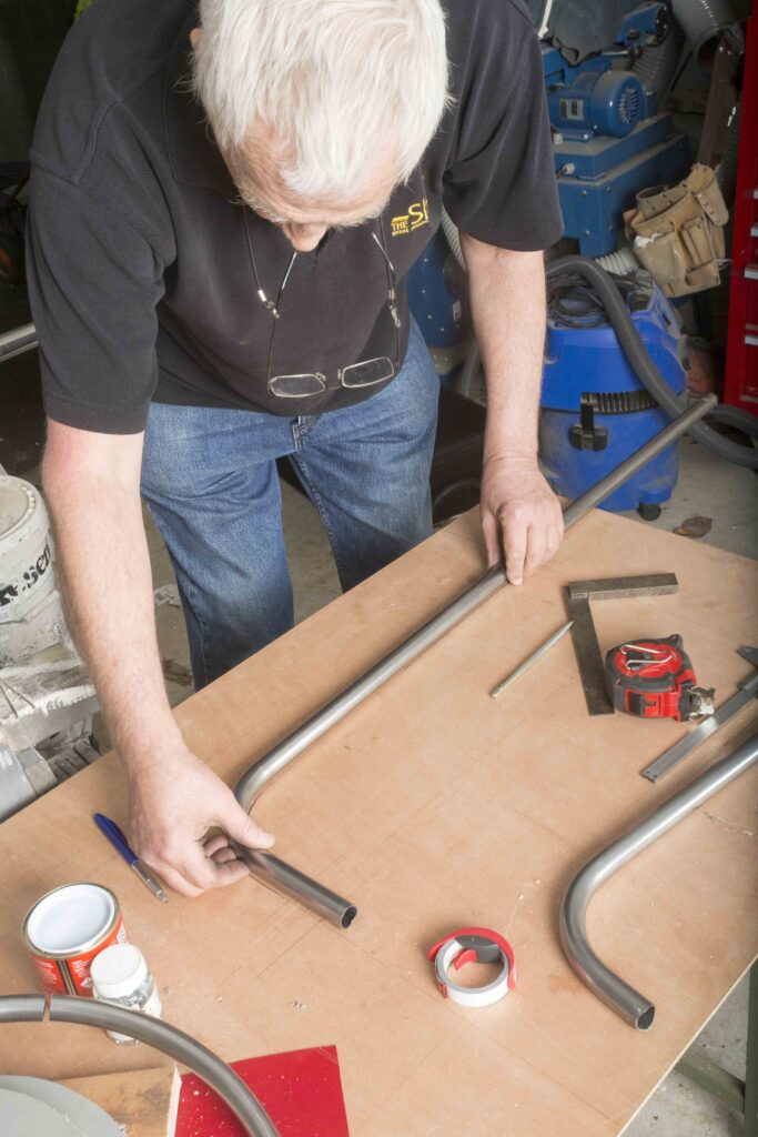
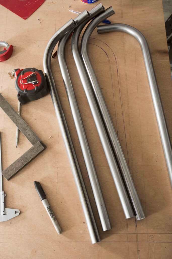
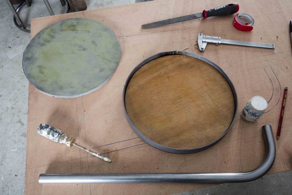
I bent the first one for practice and to work out the size and angles for the legs. I want a certain amount of splay in the legs to prevent the stool from easily toppling. The legs will be held together at the base with a tube bent into a circle.
The ring was the next issue I needed to solve. The Bramley Bender won’t bend tube into a circle, especially a 400mm-diameter one. I couldn’t really see how to do this and I did look for a roller but the only person I know with one has no formers for round tube.
The alternative was to get one from a workshop that possesses a proper tube former. With the right machine it’s possible to have a length of 22.2mm tube turned into several rings in a spiral shape and then cut them out one by one. However a machine like that was beyond my budget and I certainly don’t have the space for it.
My luck was clearly in as I managed to secure a freshly bent ring when I went to enquire if my friends at Special Wire and Tube in Onehunga could bend the tube into a ring. They couldn’t but they did know someone who could and it happened they had just had some bent into the ideal size for me – 400mm diameter. I would recommend that unless you were planning to go into production you too should look to find a company that has a proper tube bender and pay to get the ring bent.
Having the ring and knowing its inside diameter, I could work out the ideal angle for the legs – about 92°. I had marked out the legs on a template using the original leg and allowing for the diameter of the ring at a certain point above the floor. I then bent each leg, being careful not to over-bend them, and tested each leg against the template.
Plan B
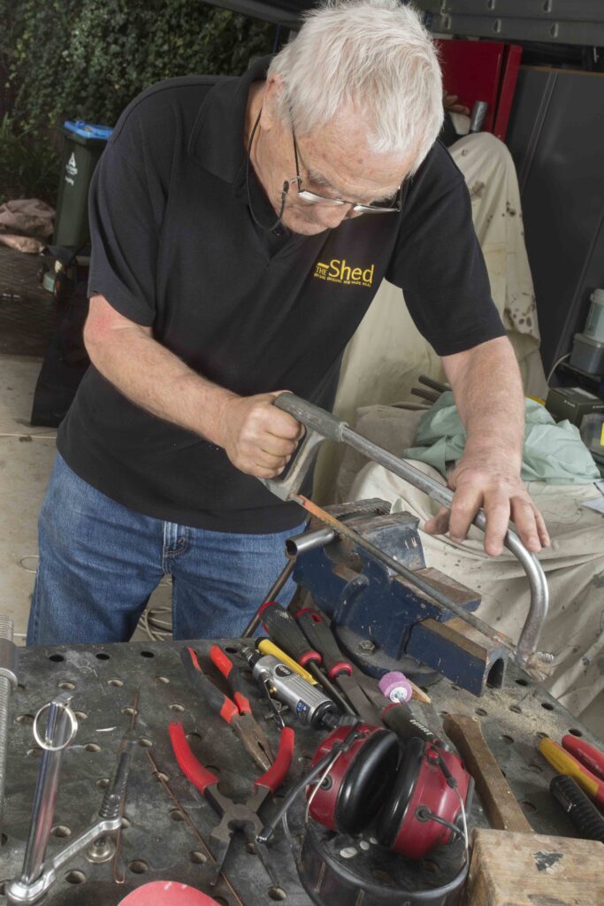
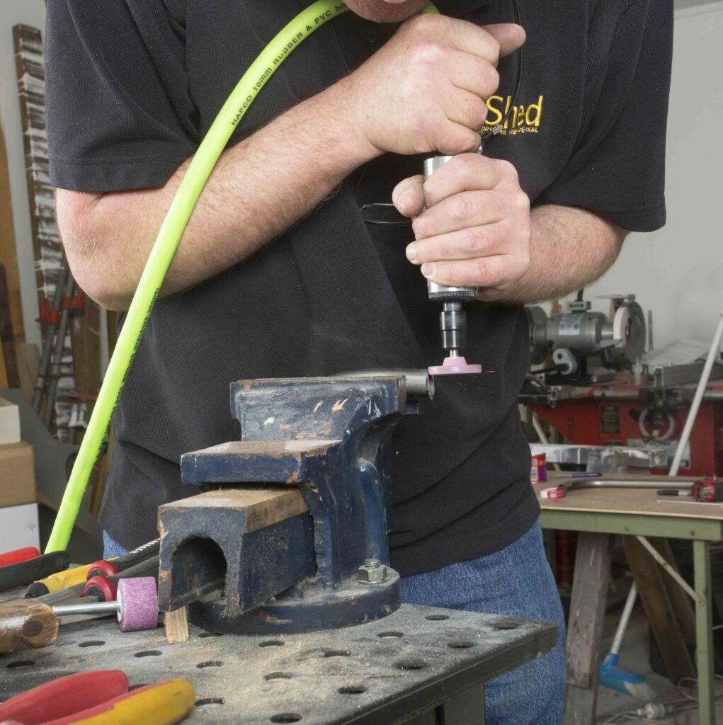
To notch the ends to fit against the nut I bought a bi-metal hole saw and fitted it to the drill press. The teeth were far too coarse and after one or two test cuts, I found it had lost a tooth. This tended to make the drill press vibrate to the point that things became loose and the saw simply wouldn’t cut. So plan B involved finding a 38mm grinding stone for my die grinder.
The only shape I could find in 38mm was a thin disc shape when what I really wanted was a barrel shape. I did have a barrel-shaped stone but in 32mm so I found I could use this to cut the bulk of the notch and finish it with the 38mm disc. Surprisingly that worked quite well but a notch cutter is now on the wish list.
The next stage was to decide on the length of the legs. This has been a vexing issue for me of late, having made a bit of blue when cutting legs for an outdoor bench a bit too long. This time I looked up similar stools on the Internet and found one with dimensions, so I followed those. In some ways it doesn’t matter too much as the seat is designed to rise and lower. I settled on a leg height of 560mm.
Getting welding
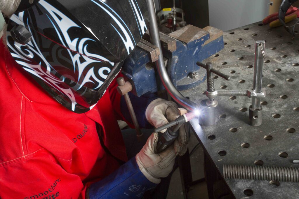
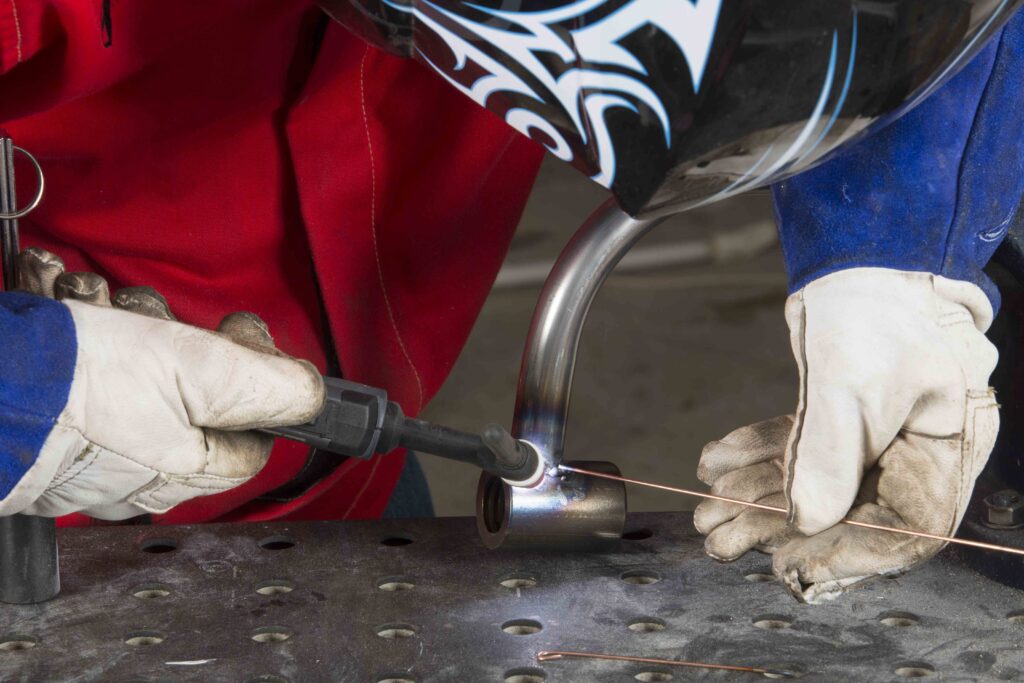
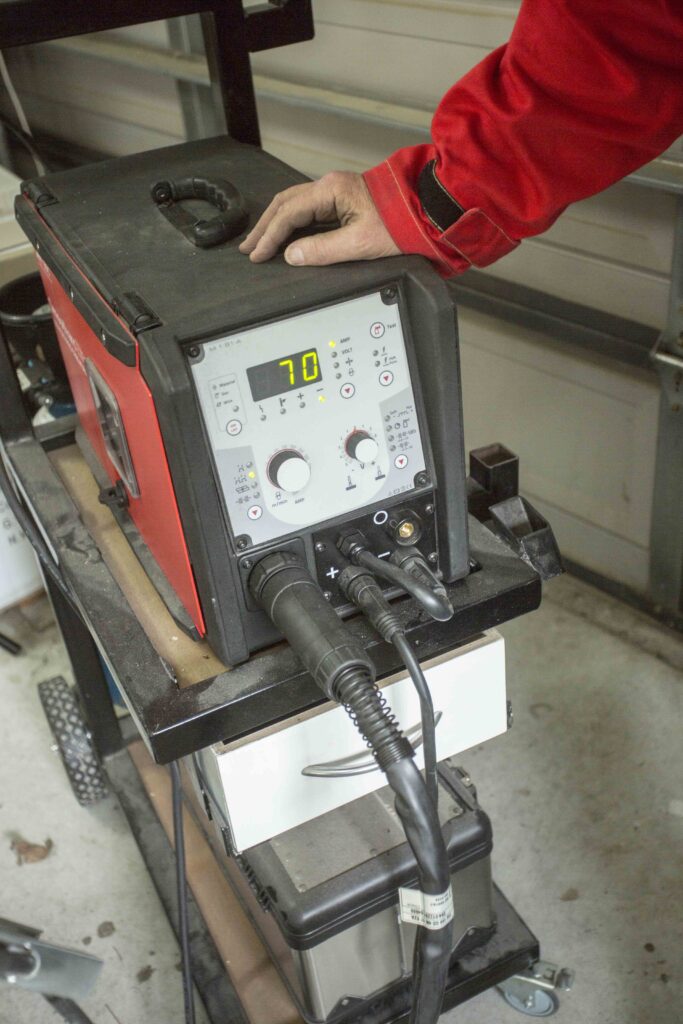
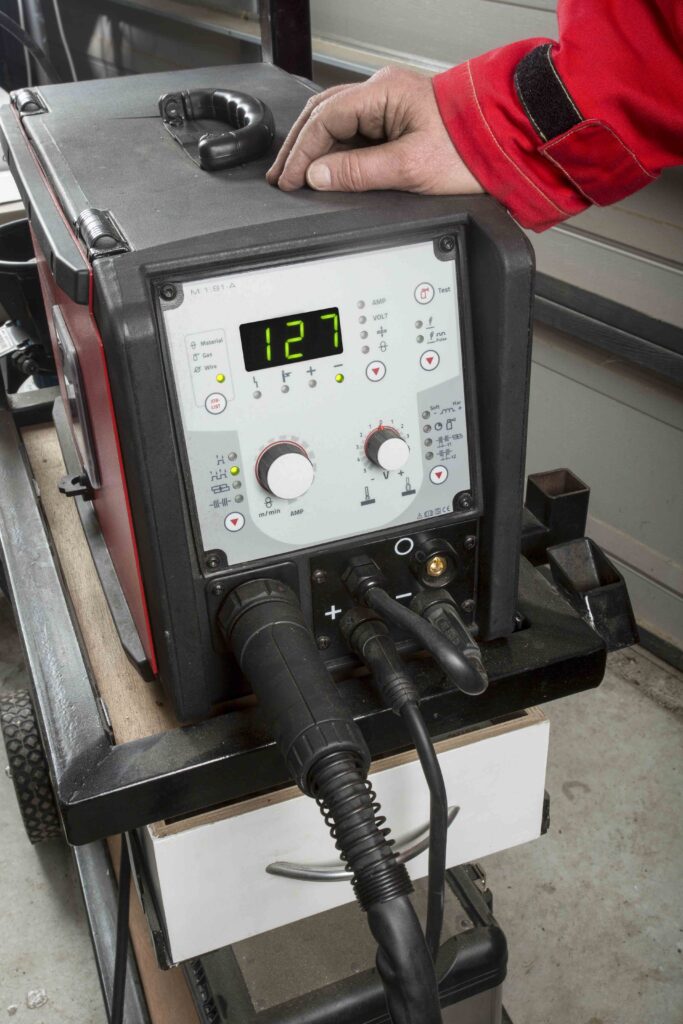
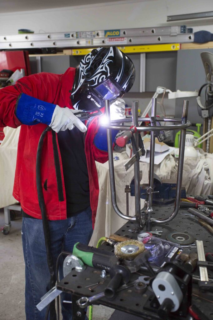
Now comes crunch time – I needed to weld the legs to the nut. I hadn’t had much time to practice my TIG welding technique and I wasn’t able to practice on the real thing. I knew that I would need at least 70 amps to melt the nut metal but this would quickly burn a hole in the tube. The beauty of TIG is you can be very precise with the placement of the arc as long as your electrode is sharp.
The ends of the electrode are sharpened on a grindstone that should be reserved for this purpose. The end of the electrode is sharpened to a point holding the electrode perpendicular, not laterally, to the grindstone. The reason that the grind should be longitudinal is so that the grind marks run to the point. That helps to direct the electrons from the arc in that direction. If you grind horizontally the arc will become erratic. With a sharp electrode you can direct the heat to the nut until it begins to melt and then move the heat to include the tube. At this point you can introduce the filler metal to the weld pool.
I have seen various experts welding in TIG and laying perfect “stack of coins” welds that require almost no clean up but I am not in that league. Plus the added difficulty to heat up and melt the nut metal before the metal of the leg made it more of a challenge. I tried first to tack the legs in place and that was reasonably simple if somewhat lacking in elegance. Then I went back over trying to lay down a stack of coins…not a chance unfortunately, although to be fair, I was getting better by leg number four. So my first attempt at using TIG was not that lovely – grinder to the rescue. I did manage to burn the odd hole in the tube too but was able to fill the holes with the filler wire. TIG is quite flexible.
It’s not a good idea for the electrode to contact the weld or the filler wire and I managed to do both with regularity so the grinding stone now has a groove in it and my electrodes are that much shorter. But it did teach me the importance of keeping that electrode sharp. Once the electrode tip gets bulbous, the arc will wander. It gets bulbous when a bulb grows on the business end from heat and impurities caused by touching the work.
So it wasn’t perfect but the legs are welded and cleaned up.
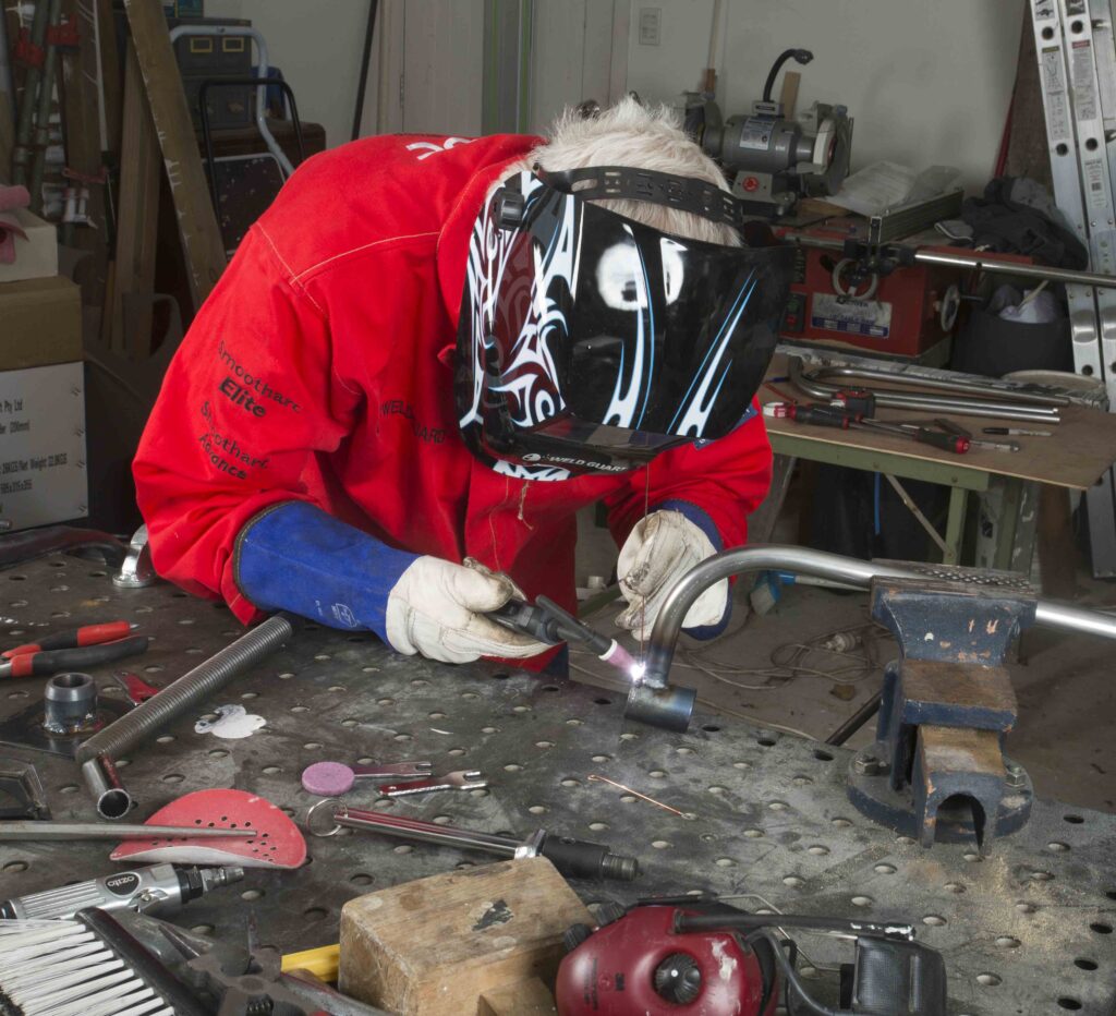
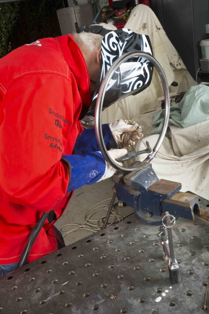
The next job was to weld the hoop that will hold the legs together and become a footrest. For this I reduced the amperage to 40 amps and clamped the hoop to close up the gap.
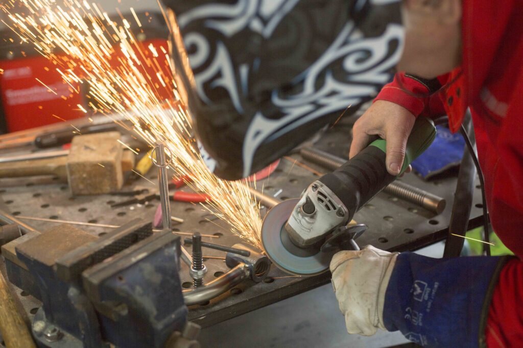
Sharpening tungsten
Grind your tungsten to a point. After you have been welding for a while, the point will round off slightly. A few bad strikes will also blunt the point and an unstable arc will occur. Resharpen the point on the tungsten.
Grind in the long direction and make the point roughly 2½ times the diameter. A 200 grit or finer grinding wheel is ideal. Good practice is to not use the wheel for other jobs as the tungsten can become contaminated, causing an unstable arc and inferior weld quality. – Greg Holster
Hidden joins
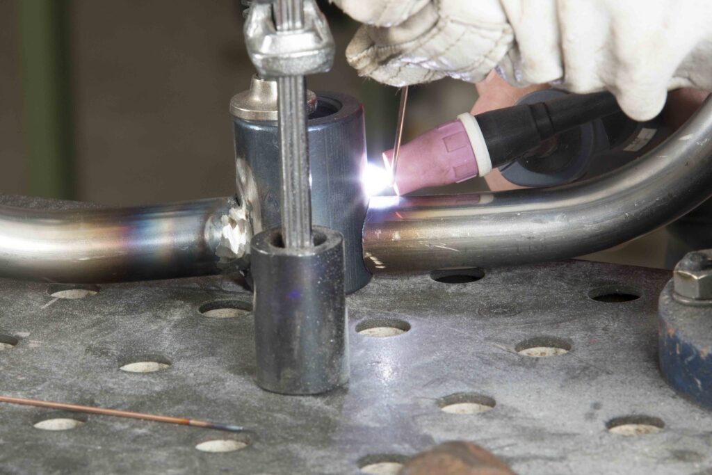
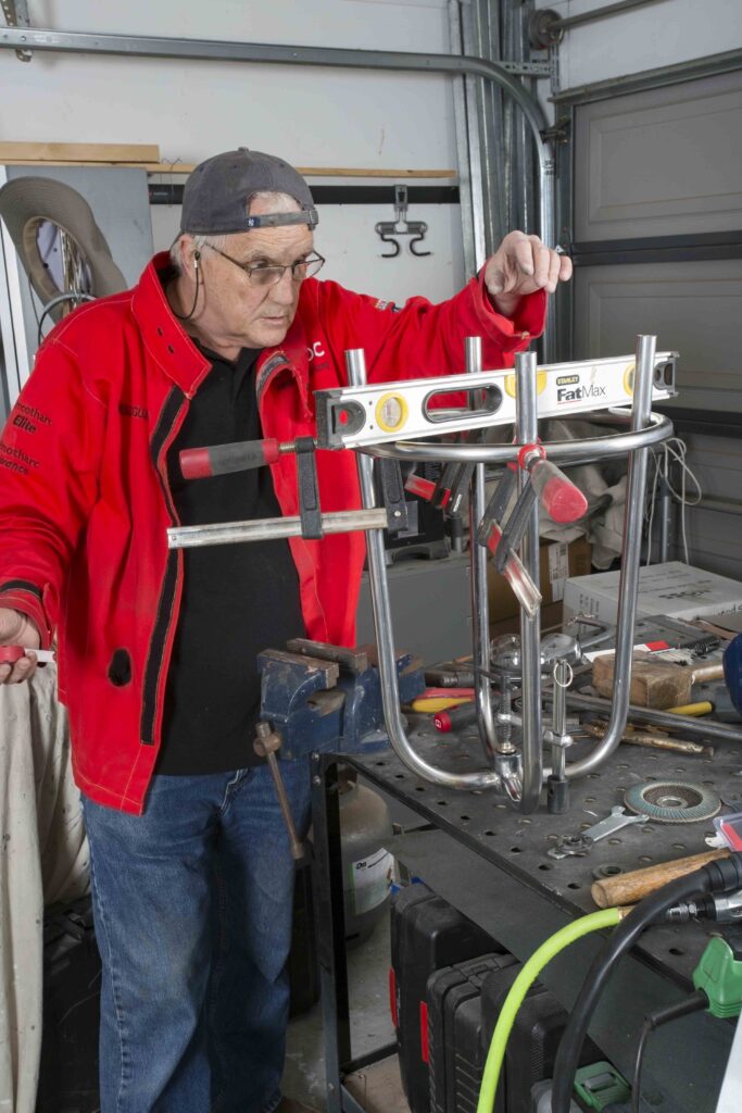
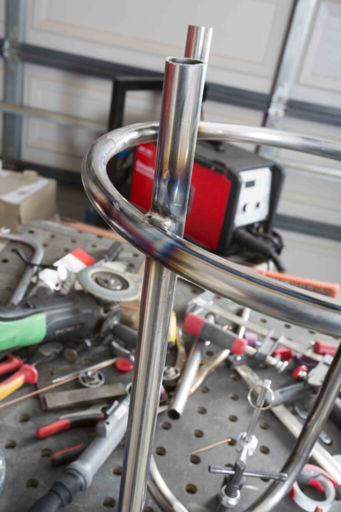
To attach the hoop to the legs I clamped it to each leg in turn, checking for level and distance off the base. With the stool upside down I welded each leg to the hoop. Welding two pipes together with TIG isn’t straightforward unless at least one of the tubes has been notched to make a good fit. In my case this wasn’t possible so I just had to make do.
I found I needed to increase the amperage to 70 amps again and increased the stickout a bit to make sure the arc could penetrate to the intersection of the two tubes. Stickout is the distance the electrode projects from the gas cup. With both tubes equally hot and beginning to create a weld pool, I added filler to the pool and moved the arc around the pool, gradually increasing the weld pool. It worked quite well and as I had performed the weld on the underside of the hoop it wouldn’t be visible from above.
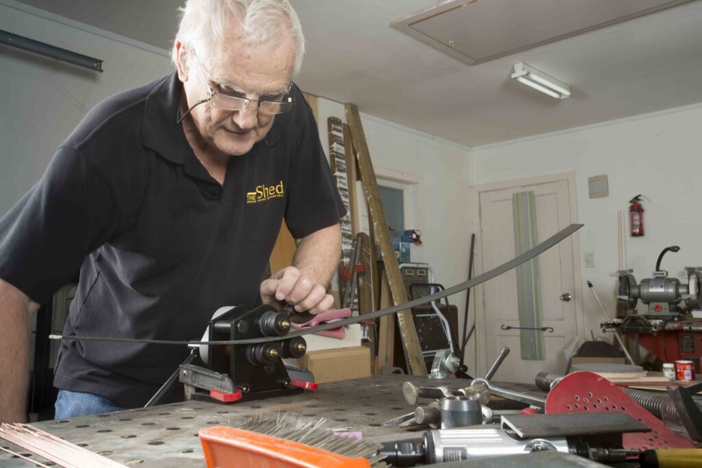
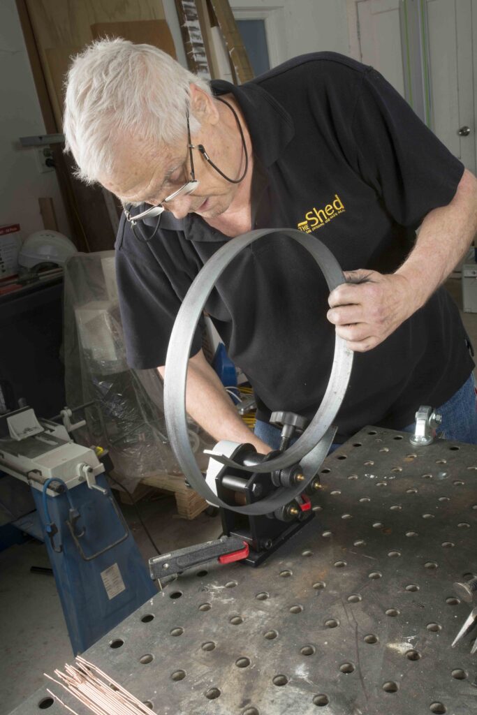
The seat I cut from 19mm ply and added a 20mm piece of closed cell foam. I also have a piece of vinyl to cover the seat. A 25mmx3 mm strip of mild steel binds the seat itself. To get the circular shape I employed yet another machine especially for the task. I purchased the little metal roller from Machinery House in East Tamaki for around $140. They are bit limited in that they can only handle mild steel up to 4mm, and 5mm solid round bar, but they do the job. I bent the strip and cut it to size and fitted it to the seat.
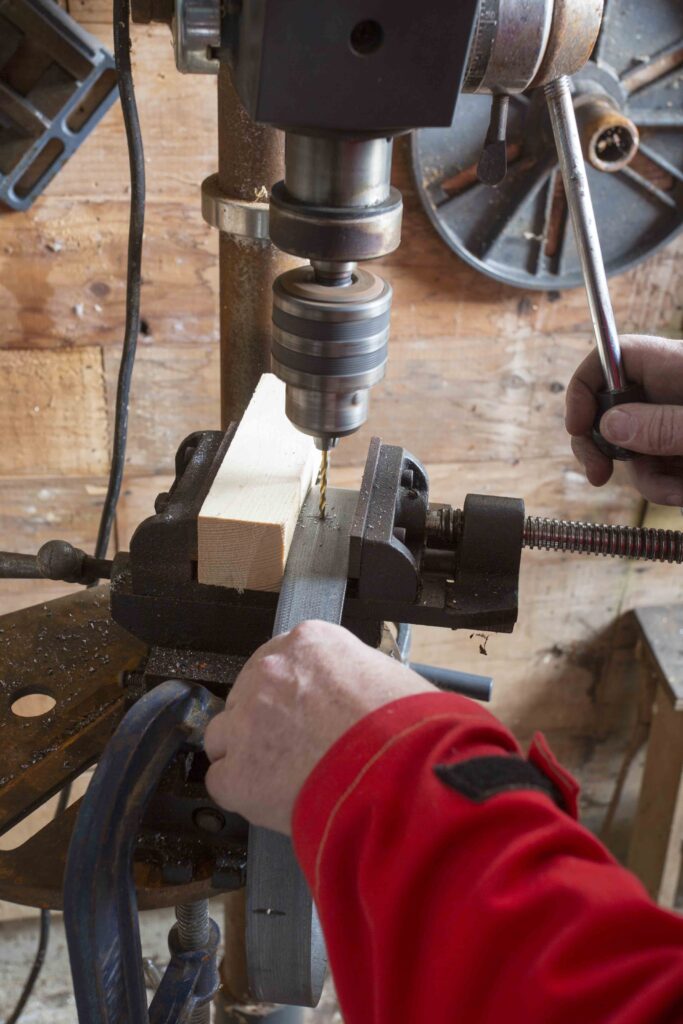
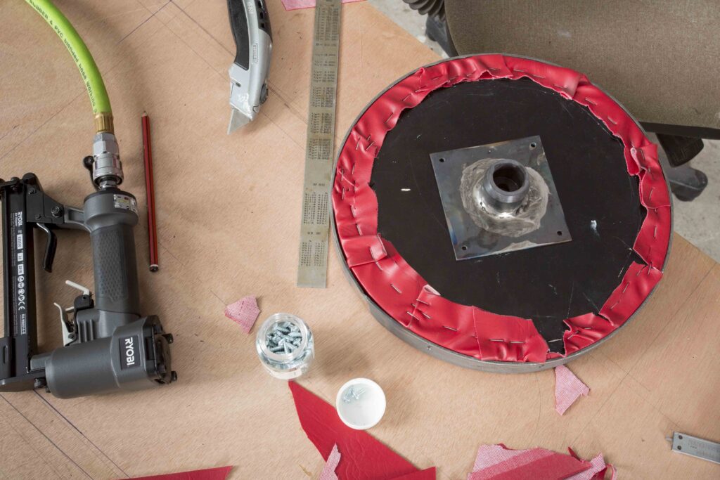
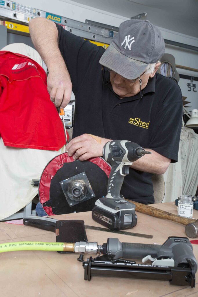
With the seat and band fitted I drilled holes through the strip for pan-head screws that would hold the strip to the seat.
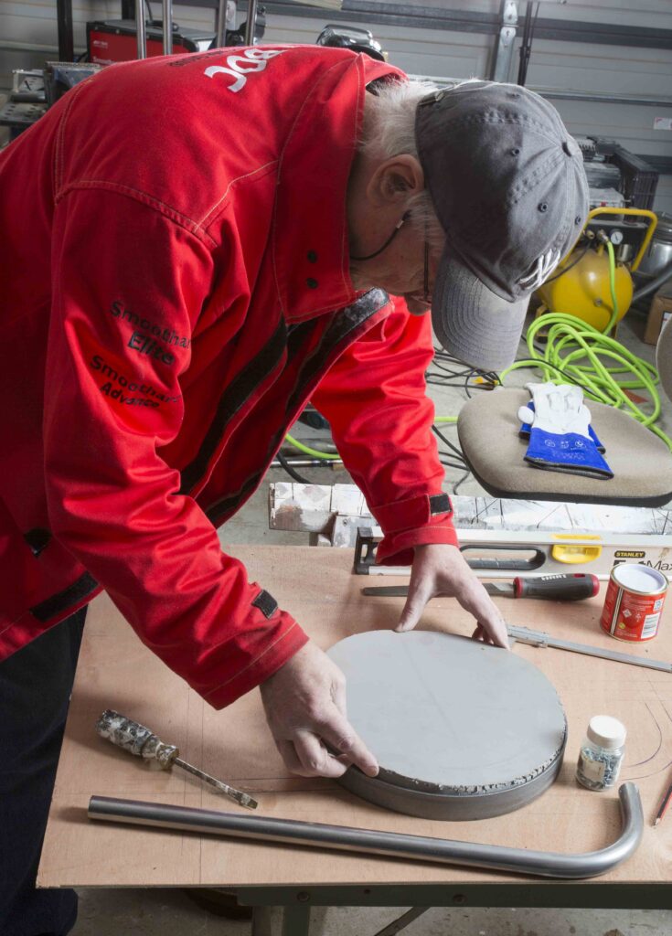
Final seat fitting
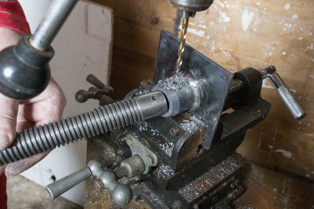
The next process was of course to attach the screw to the seat. For this I had obtained a piece of 3mm mild steel and cut a bit to 100mm square. I drilled holes in each corner for the fixing screws. I happened to have a piece of round bar that had been drilled for an earlier lathe project demonstrating the boring bar, and it happened to fit the screw very well.
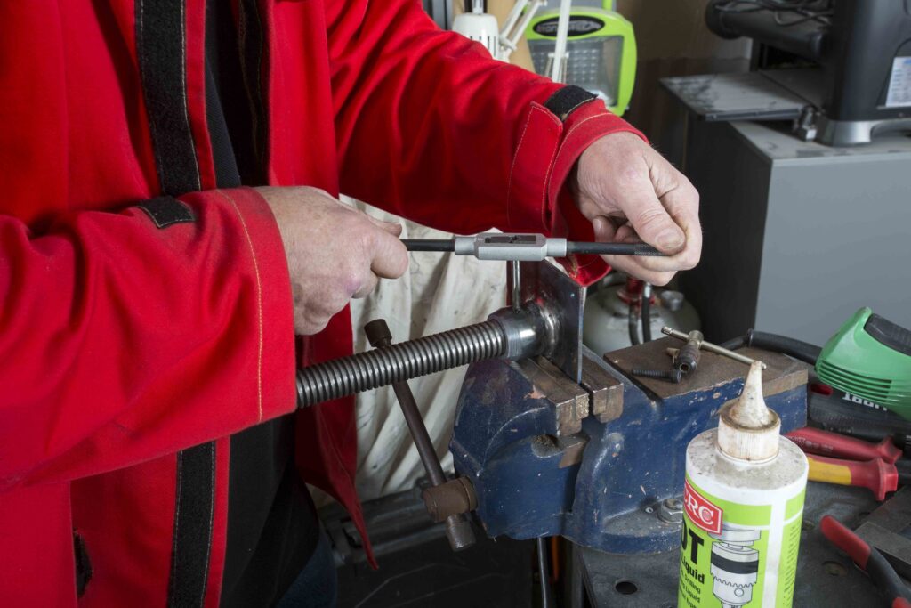
I could have welded the screw to the sheet but I thought it better to attach the ready-made socket. It gave me some experience in welding a heavy piece to a lighter piece of steel. In fact I used this piece as a practice before I tackled the attachment of the legs to the nut. With the socket attached I drilled a 5.5mm hole through it and the screw and tapped both to fit a 16mm socket-head screw. The idea is I can remove the seat if I wish at some later date.
One problem I discovered trying to refit the screw to the nut after having spent some time welding the legs was that the heat had obviously caused the nut to distort a bit and it took some considerable winding of the screw back and forth to free it up again. In future I will weld the legs to the nut with the screw in place to help dissipate the heat.
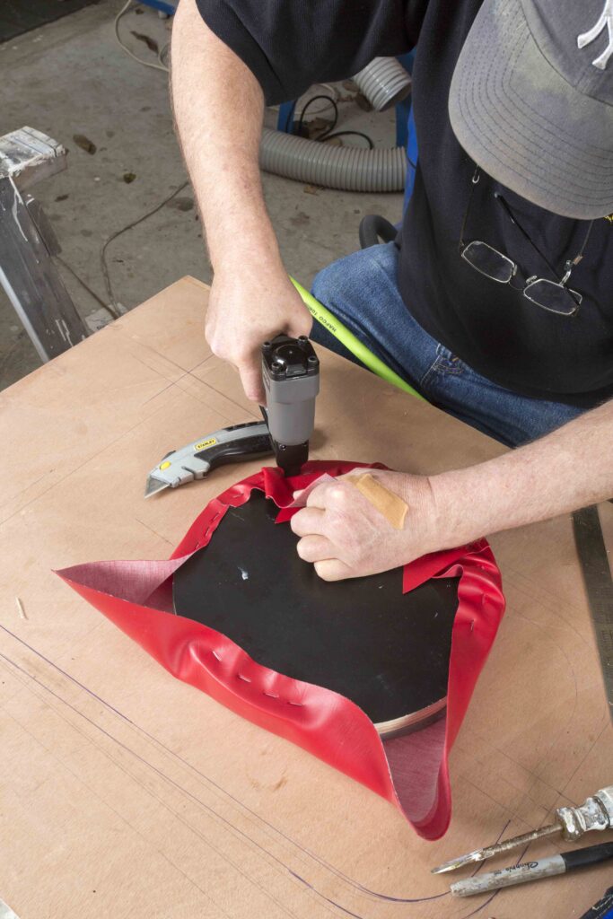
I glued the foam to the seat blank with contact cement and used the iron ring to help locate the foam precisely. I removed the ring again and covered the seat with marine-grade vinyl. I am not that experienced at upholstery so my efforts must look a bit amateur and more than a little clumsy.
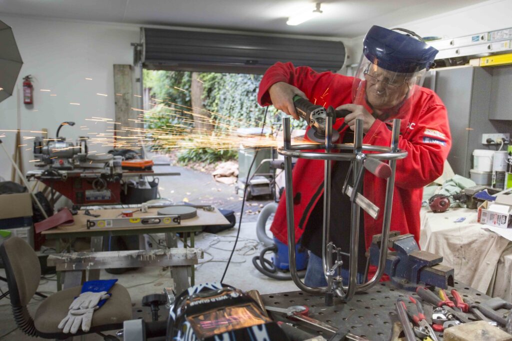
To finish the ring I have cleaned it up with a brass brush in the angle grinder and after careful masking I painted it black. I also used the brass brush to remove the colouration from the legs around the welds. This tended to give the whole thing a satin look so I proceeded to run it over all the exposed steel to give it a homogenous look. I added the plastic feet that I got from Hi-Q Components in Albany and it’s finished.
The results
Overall I am very pleased with the stool. I am especially pleased with the way the welding turned out. Remember I have had only minimal practice with TIG and this demonstrates what any rank amateur can achieve with a bit of patience and a handy grinder. My welding did actually get better by the end of the project and I am sure if I make a few more of these, which I intend to do, I will be far more accomplished by the end. In future I will use a shorter screw – 200mm-250mm should be plenty – and I want to alter the composition of the ring around the seat; maybe something lighter and shinier next time – thin stainless perhaps. TIG is well suited to welding stainless.
It has been a project that exposed me to all the practical uses of TIG welding and TIG is addictive. Not flash and dash like MIG but quiet, methodical and precise. It pays to have some ventilation available though. TIG produces a lot of ozone and you can smell it. Ozone is not really that good for your lung function.
TIG welding rules
TIG welding is similar to gas welding. There are a few simple rules to keep in mind to ensure you get a good result.
- Thoroughly clean the area to be welded. Cleanliness cannot be stressed enough. It’s not like MIG or stick where you might get away with welding over a bit of rubbishy or unclean metal. If you try to TIG weld over rust, paint, or heavy oxide you will contaminate the tungsten electrode and the weld pool.
- The amount of tungsten electrode stick-out needed? As a rule of thumb, stick-out should be half the diameter of the nozzle orifice. I always add a couple of mm, so I can see more easily.
- What level of argon gas flow should you use? With low amps and thin material up to 6mm thick, start at 8-10 litres per minute argon gas flow. Use a higher flow for bigger amps and heavier material.
- Use argon gas only, not the argon mixes commonly used in MIG welding.
- Which tungsten types should you use for the electrode? Thoriated, ceriated or lanthanated for DC, and zirconiated for AC aluminium welding.
- To set up and test that the settings of your machine are correct, try welding some scrap metal first. You don’t want to blow a big hole in something you want to keep.
- Feed the filler rod into the weld pool. Many learners will shove it into the arc and hope for the best. Not so! Just dip the wire into the leading edge of the weld pool. That’s where your concentration should be.
Prepare weld
Clean: Make sure that the weld joint area and also the filler rod are as clean as possible. This is an important preparation. Remove all oil, grease, paint, rust, and dirt. Contaminants such as these may result in arc instability, contaminated welds and/or contaminated tungsten.
Clamping: Clamping may be needed if the work piece cannot be held during tacking or welding. Remember you need both hands for TIG welding.
Tack welds: On thin materials, it is a good idea to make short 2-3mm tack welds close together, as the heat will distort the joint as it is being welded.
Scratch start
Hold the TIG torch in your hand at a 70° or 80° angle. Make sure that the tungsten is off the metal by approximately 3-6mm. Don’t let the tungsten touch the work piece at this stage. With a gentle backward scratching motion, strike the tungsten onto the earthed material to be welded. A weld pool will start forming. From here start moving forward at a regulated speed. You will soon see what speed suits your amperage.
Welding
Now you can try this using a TIG filler rod. Hold your filler rod lightly in your opposite hand so that it rests horizontally at about a 15° angle from the material. Wait for the molten pool to form on the base metal and gently dip the filler rod into the weld pool. As you move forward, you will see the weld bead starting to form. If your machine has a high-frequency start, there is no need to touch the parent metal. – Greg Holster

