The Shed Logo
Search
Close this search box.

Make a handy English wheel

So it was time to start fabricating my own parts and for that I would need a so-called English wheel machine to mould the tank, guards, seat pan etc. But buying such a machine was “off the budget” as they come with a hefty price tag. The next option was to build one. With not a lot of plans available, I could see that I’d have some homework to do.

Mould custom sheet metal parts with your homemade English wheel

Wheeling sheetmetal. Leif Haseltine shows us how to use his his English wheel
Wheeling sheetmetal. Leif Haseltine and his English wheel

I’m a 32-year-old from New Plymouth and have been involved with engineering ever since I can remember. I think I started off sweeping the floor in Dad’s workshop at about eight years of age.
My introduction to welding was sneaking into the workshop, finding a spare helmet and watching the big boys weld. It was cool ’cos they drank beer, partied, had V8 cars and hot chicks. I wanted to be like them. I finally got my chance to try it out one day and started cobbling knives and swords together (which I still make, but the welding’s better now). The first sword I ever welded still hangs on the shed wall.
I’ve worked in the engineering trade off and on here and in Australia, so am no stranger to making things of steel. Now I make what “I” want and have done numerous projects over the years.

Jacking shaft—the start

Harley

My other interest is motorcycles and my current model is a ’91 Harley Softail. It looks like the other thousands out there as you can only change so much with “bolt-on” products. So it was time to start fabricating my own parts and for that I would need a so-called English wheel machine to mould the tank, guards, seat pan etc. But buying such a machine was “off the budget” as they come with a hefty price tag.
The next option was to build one. With not a lot of plans available, I could see that I’d have some homework to do. The first step was to think about what I would use it for: custom motorcycle parts, tank, guards etc. That would give me an idea of the size I would need, approximately 600 mm throat with 150 mm x 50 mm top anvil wheel and 75 mm x 50 mm bottom anvil wheel.
The wheels all seem to be pretty standard on a machine of this size. I was fortunate to find a set of wheels with bearings on TradeMe, so that was one hurdle overcome as I don’t have a lathe (it’s on my Xmas list).
The main frame came from offcuts at an engineering shop I had worked at (cheers, Pete). This was all 100 x 50 x 6 mm RHS. The only thing to figure out was the jacking shaft. I wanted to use off-the-shelf materials for this. If I had to get anything machined it would be all cost, and besides I couldn’t really say that I had “made” it then, could I? Buying the wheels was enough of someone else’s efforts in this project.

Square 40 mm plate on bottom of shaft
Notch in bottom plate for RHS seam
Shaft slides inside RHS
Final grease before fitting
Collar welded to fit shaft

Jacking stud

The jacking stud is the only real mechanical part on this machine. The wheels are based around it so to me it was a good place to start. I used a solid 1 ¼” (32 mm) shaft with a 1 ¼” (32 mm) collar to fit, welded to the 50 x 50 x 5 mm rectangular hollow section (RHS) at one end because you can’t buy two box sections that will fit neatly into each other. At the lower end, I welded on a square piece of flat bar, then sanded it to a nice snug fit. This allows the shaft to slide up and down but not to turn.
You must grind a notch out to allow for the seam inside the RHS. Take time with this as it will affect your final outcome. You don’t want your wheels slopping around when you are trying to “wheel” some sheet metal. It will only result in a shoddy job and a pissed-off operator.
The size of the threaded rod you use to jack it up won’t matter. I used 32 mm because that is what I had in the shed and I think it worked out perfectly, nice and firm with next-to-no play in the thread. I am sure a 12 mm bolt would be sufficient.

How to make an English Wheel (9)
Welding nut for threaded rod.

Notes to the drawing

The key point to making this English wheel is to keep both wheels and the jacking shaft on centre. If you need to, work the other dimensions off the centre line.
The steel for the main frame, including the gusset supports for the cross-arm, is all 100 x 50 x 6 mm RHS. The jacking shaft is 50 x 50 x 5 mm RHS and the front legs 40 x 40 x 5 mm RHS.
The bolts which act as the wheel axles are supported by 50 x 10 mm flat bar. The washers on either side of the wheels are whatever you have to suit the bolt. I allowed 5 mm clearance from the curve of the wheels to the top and to the base.
It took a while to find a 20 mm bolt (countersunk) for the 150 mm diameter top anvil wheel but you need that or something similar to suit the bearing. The bottom anvil wheel has an M 12 countersunk bolt, or you could use something that also suits the bearing.
The welded, U-shaped cradle from 50 mm x 10 mm flat bar for the lower anvil wheel sits on a collar to suit the 1 ¼” solid bar.

Tacking handle rods on nut
Test fit of bottom of shaft

Grease

On the final fitting of the jacking stud, I coated the lower end of the shaft with anti-seize grease just to help it slide nice and freely. Remember that it’s gravity that will lower your wheel once you wind the thread out and you don’t want it to stick.
Once you are happy with the fit, both the nut and the collar can be tacked in place at either end of the RHS. If you’re really confident you can fully weld them on. I didn’t, as I like to see the complete finished thing fitted together before I fully weld.
I removed the grub screw that is supplied with the collar and put in a grease nipple. I figure a light greasing every now and then would do it good. With the jacking shaft complete, all we need now is a handle to turn the thread.
To make this handle, I used a 32 mm nut with equal pieces of 16 mm solid rod welded onto on all six sides of the nut. I wanted to make this heavy as I just kick it with my boot when I need more or less pressure on my work.
With a quick test fit, this should be fine. The handle will be welded to the threaded shaft but not at this point. I found I still had to make the rest of the frame on a flat surface and with this handle already welded on and in the way it would have been difficult

Bottom anvil parts
Sample assembly with flat bar
Lower anvil base and collar
Centering collar
Collar fixed on anvil base
Test fit

Cradle

The lower anvil wheel cradle will hold the lower radial wheel (on its axle) onto the jacking shaft, so the same 1 ¼” (32 mm) collar is used for fitting it to the shaft. The grub screw remains in this time to provide a way to secure it to the shaft. I used a counter-sunk bolt as an axle for the wheel, tapped a thread into one of the side plates and trimmed the bolt to a flush fit both sides. You don’t want to be wheeling away and catch your knuckle or fingernail on a bolt head (it hurts).
To tack this bracket, I used a piece of 50 x 50 mm RHS for mock-up instead of the 50 mm-wide wheel as I didn’t want welding splatter or sparks in the bearings.
IMPORTANT: make sure the collar and cradle are all central to each other. With this piece done, it is time for the main frame again. I chose not to fully weld at this time.

Assemble frame flat on bench
Tack-weld cross-arm

Main frame

Putting together the main frame is a simple thing to do, but take all time needed to make sure it is all square. Making it on a bench is good as that provides a nice flat surface. I know that my bench is square, so I used its outer edges to G-clamp my piece to, measuring against the squareness of the bench whenever possible. The frame can be tacked up.
Do not worry about any gussets at this stage as they can be done at the end. The main focus should be keeping the jacking shaft square to the top frame as this is where the top wheel will be mounted and these must be both central to each other.
The same 50 x 50 mm RHS is used to mock up the top wheel cradle. Again with this, I used a counter-sunk bolt, but as I didn’t have a 20 mm tap to put the thread in I welded a 20 mm nut to the side plate. I then tacked the cradle in place and made sure it was square and central to jacking shaft.
When I was sure, I checked again as this part is one of the most important, and if not right, will give you disappointing results in machine performance and your final work.
Once you are satisfied, begin the final welding of all the main frame

Final measure
Upper anvil tack-welded
Leif checks. Frame and jacking shaft must be centred and square.
Leif assembles wheels

Legs

Now all that is left is the two front legs cut to size for which I used 40 x 40 x 5 mm RHS. The rear leg is part of the main frame. This will be a three-legged model which will provide better stability than four legs on an uneven floor. 
I tacked the mainframe to the centre of bench at right angles to provide an even, flat surface for the legs to lie on.
Once you are happy with the leg position, fully weld them. Now we should have something that resembles an English wheel, and can do the final fitting of lower anvil wheel to the shaft.
I completely assembled the English wheel and checked the alignment of the wheels and the operation of the jacking shaft. The test run on a piece of 1.2 mm-thick sheet produced great results. Time for the clean-up and paint.
With a flapper disk on my 5” grinder I smoothed all welds and any sharp edges that I might catch on while wheeling.
 I chose Blue Hammer Coat paint to provide an excellent finish and give it that professional look. I am a big fan of finishing a job properly. If you are going to take the time to make the thing in the first place, go all the way and buy decent paint; finishing touches make all the difference. Doing it right from start to finish will give you a job that you can proudly say you made, and it will provide you with years of service.

Grease nipple replaces grub screw
Action at last

Share:

More Posts

Making a die nut

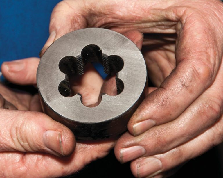
A die nut is created with interrupted sections of thread around its internal diameter. Die nuts are simply screwed onto the threaded part. As they are wound down, they cut away any of the screw thread that is bruised (bent over) or out of line. A die nut cuts irregularities and scrapes off the dirt from the thread it is being used on so needs cutting edges, which are formed by the cut-away places.

Knifemaking by Leif Haseltine

The design for this article is my everyday carry knife, a four-inch (100 mm) dropped hunter—an all-round knife whose blade is ample, large enough to skin that buck and small enough to carry all day without getting in the way.