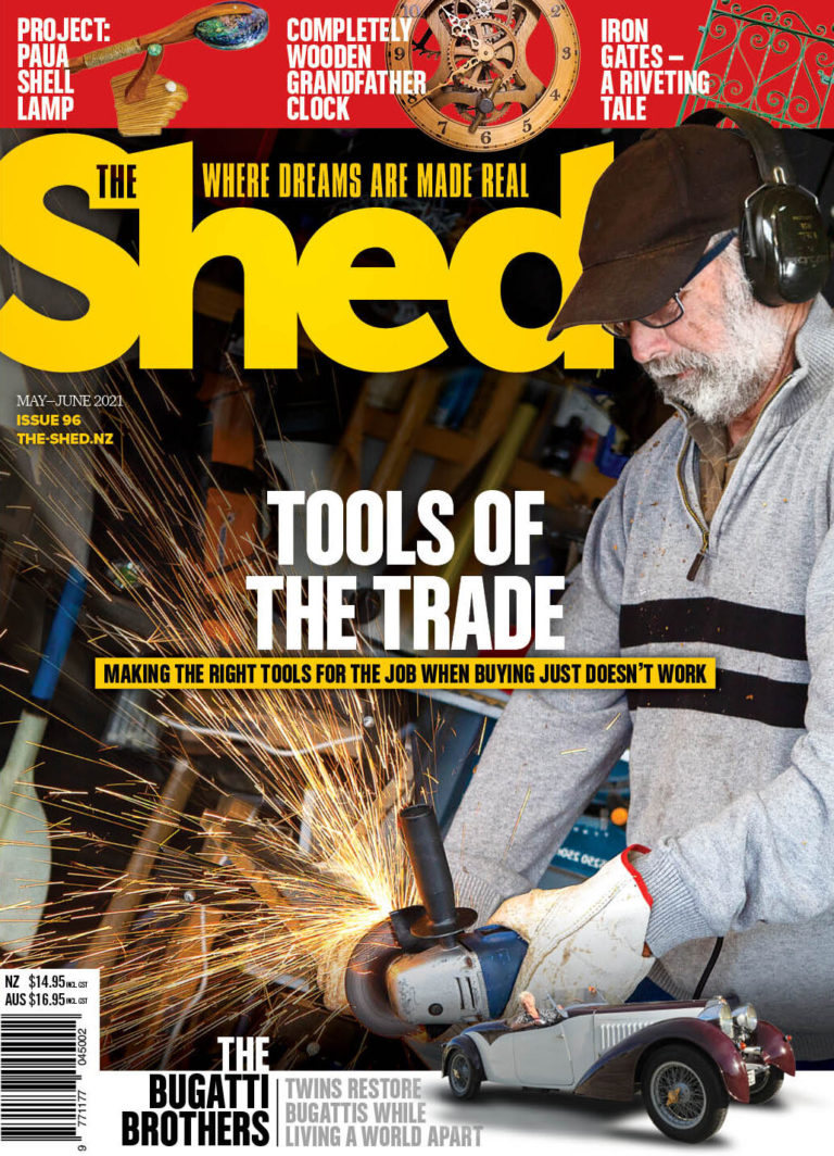
Our cover story in the May/June 2021 Issue No. 96 of The Shed is about a sheddie who decided to avoid spending a fortune on tools for his new career and instead make his own. Why? Because he could, and it saved waiting months for delivery in these Covid ravaged times. Plus there were considerable financial savings to be had.

Our cover story in the May/June 2021 Issue No. 96 of The Shed is about a sheddie who decided to avoid spending a fortune on tools for his new career and instead make his own. Why? Because he could, and it saved waiting months for delivery in these Covid ravaged times. Plus there were considerable financial savings to be had.
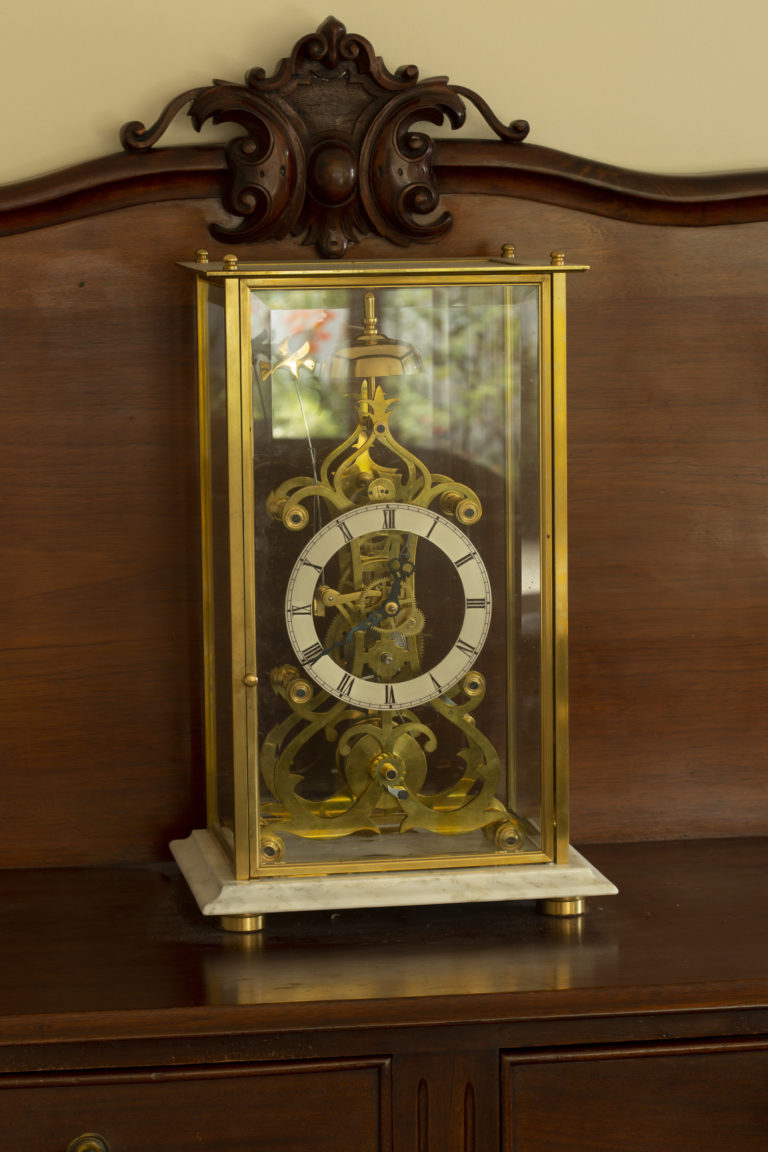
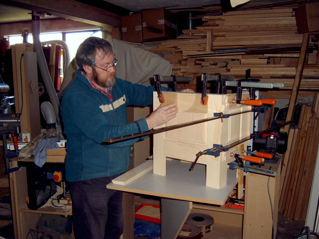
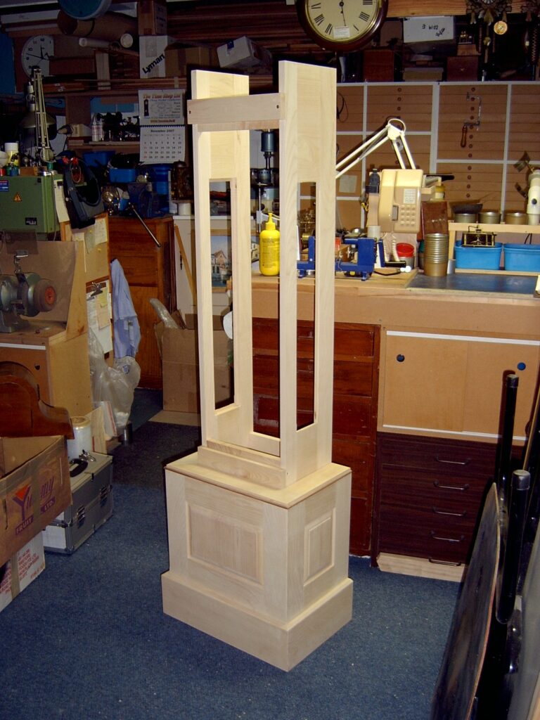
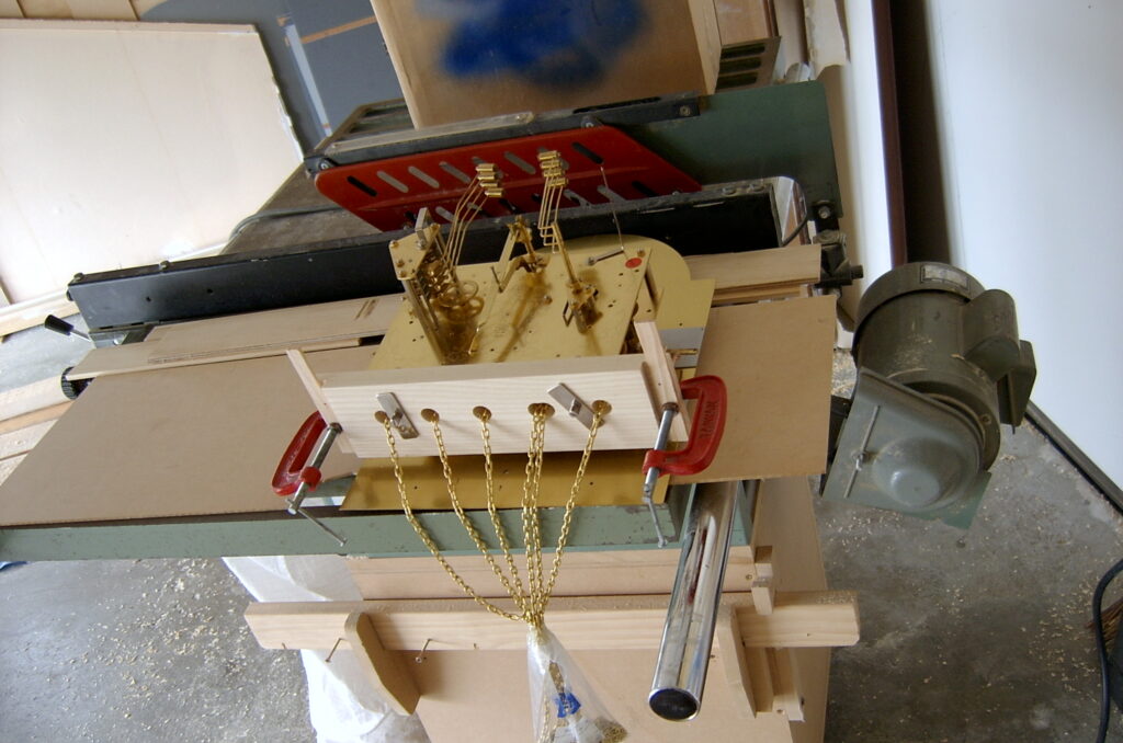
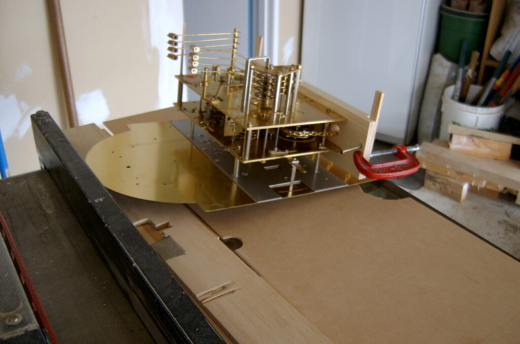
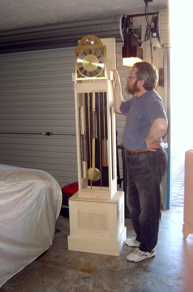
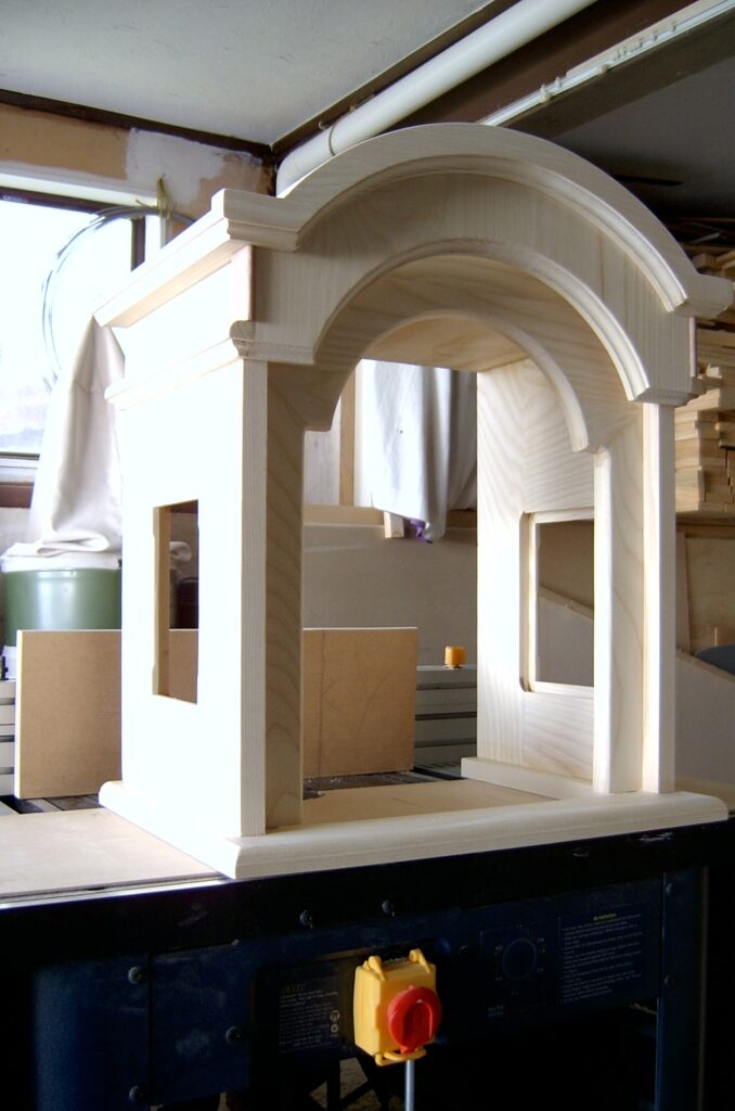
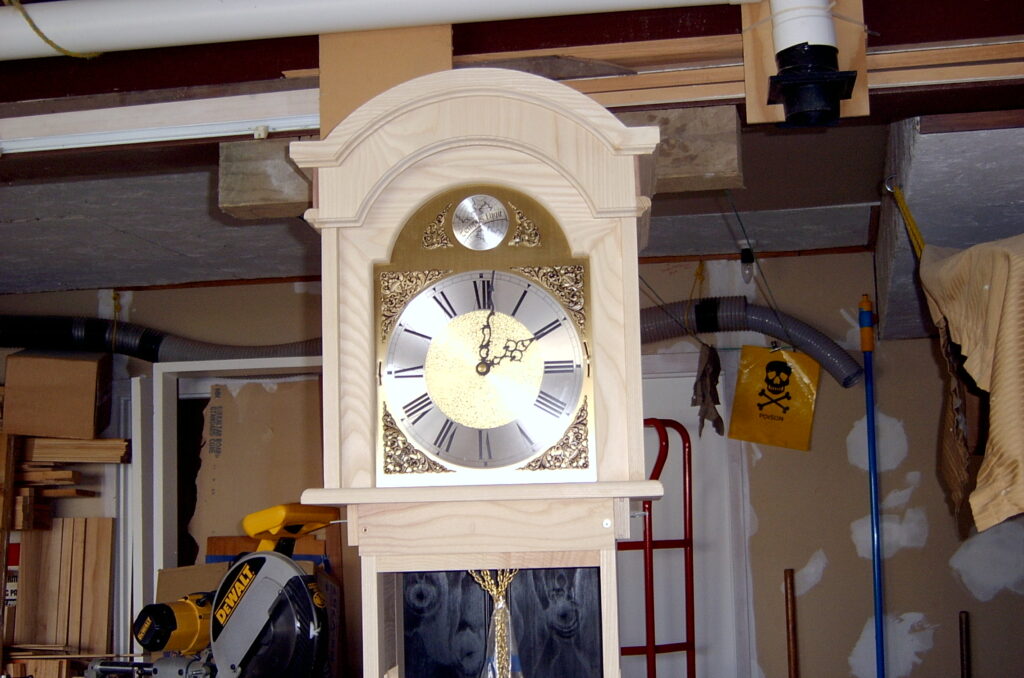
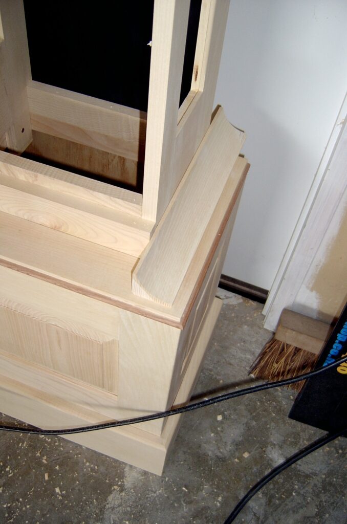
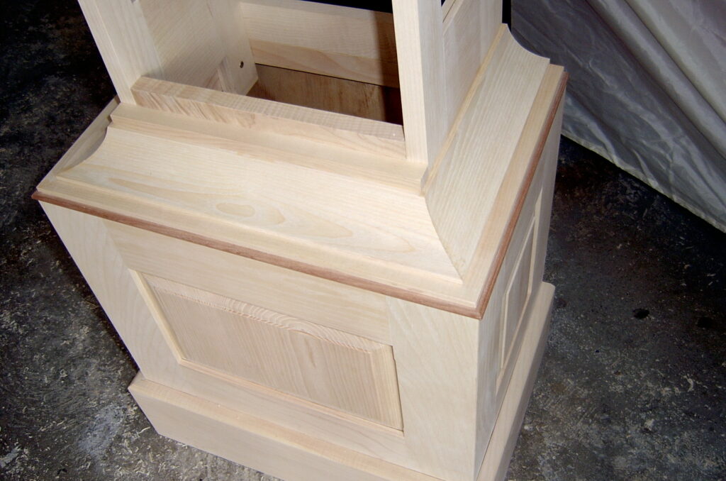
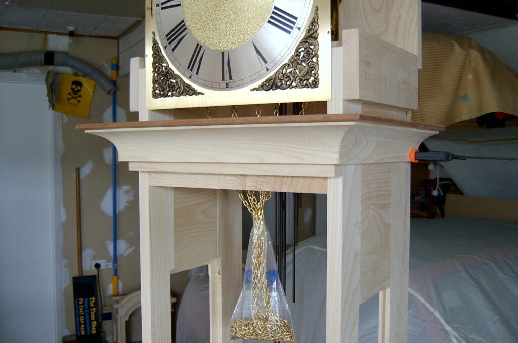
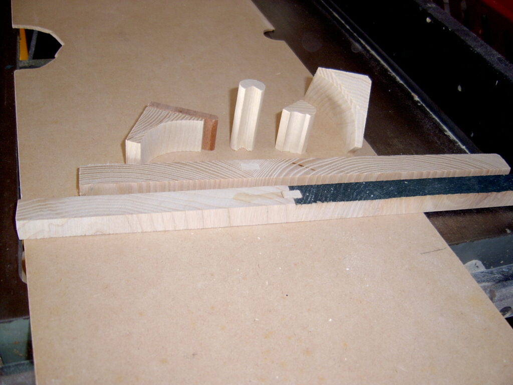
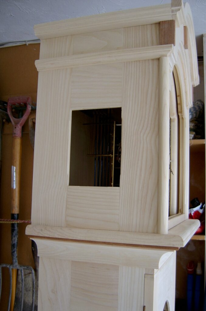
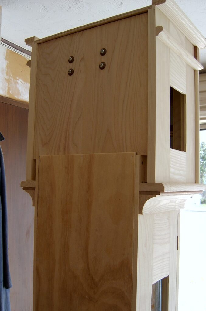
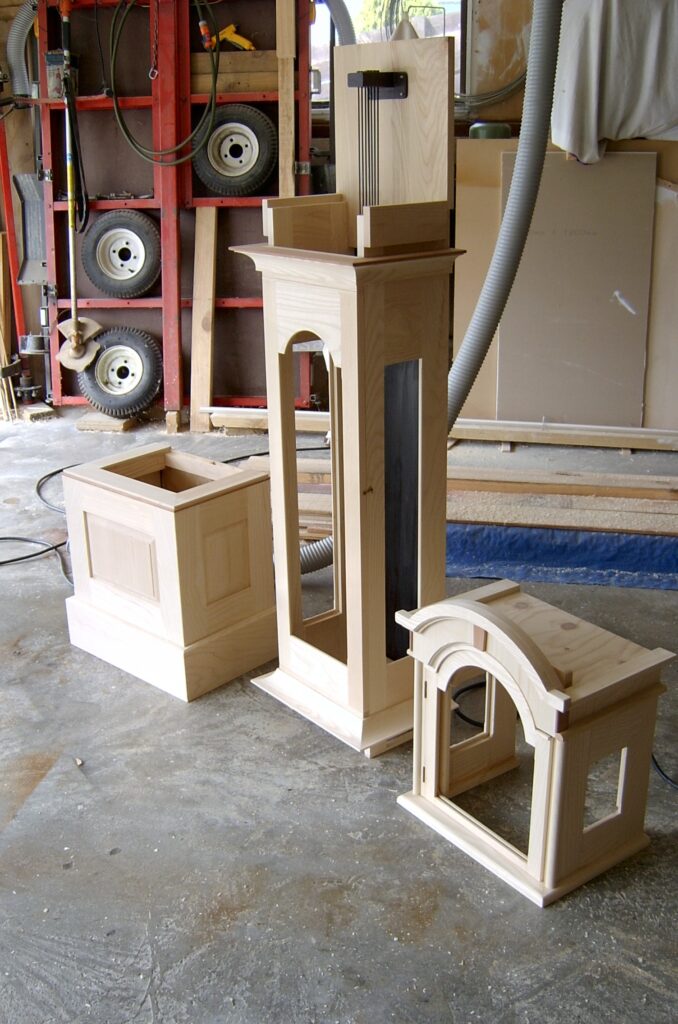
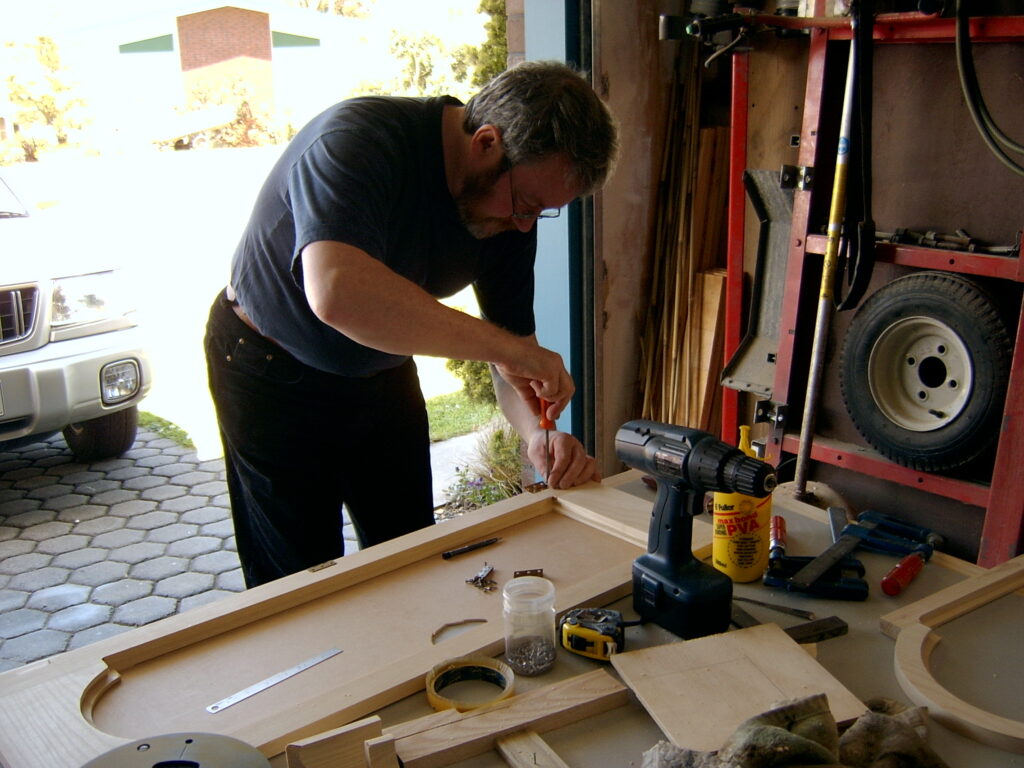
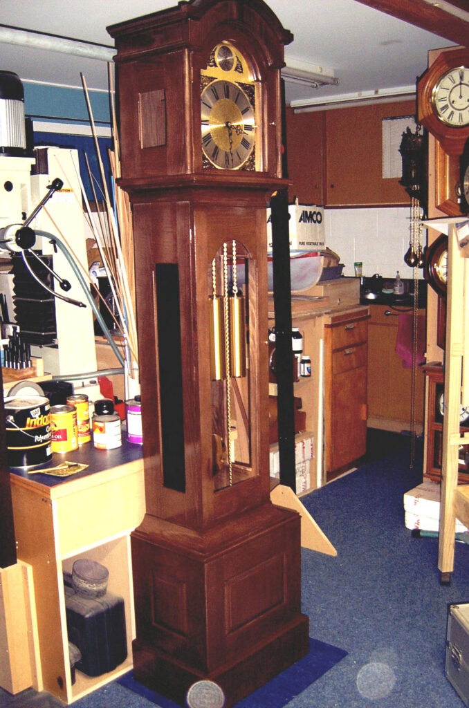
Aucklander David Curry shares with us his shed where he makes skeleton clocks, stationary engines, tools and more.