Welding: Standing to attention – lathe bench build part 2

I ordered some drawer slides of the appropriate length (350mm) and worked out the width of the slides and thus the width of the drawers. The drawer slides are rated at 45kgs. I couldn’t be sure what weight I would be likely to load but this should suffice. I elected to run with eight drawers and make the second opening in the frame a cabinet to house larger components like the four-jaw chuck. After some fiddling I settled on two drawers each of 75mmx70mmx60mm, and 50mm high, separated by 10mm. I bought three sheets of cold rolled steel 1mm thick. This is within the limits of the panbrake and I had hoped the material would be stiff enough given that the drawer had to span over 500mm width. I broke the material down into half sheets to make it easier to handle.

Top drawer 
In part 2 of our lathe stand build, a few lessons are learnt making the drawers 
By Jude Woodside
Photographs: Jude Woodside

A while ago I ordered a pan brake from a well-known local Australian engineering retailer with a view to making a set of drawers out of steel sheet. I assumed it would fairly straightforward – simply bend the drawers into shape using the fingers on the panbrake. A brake would make everything accurate. What could possibly go wrong? 
I had made the stand for my lathe (part one of this article; Issue No 78) with the idea of adding drawers and a cupboard to the base to store all my lathe and mill tools, and ostensibly for the tools I envisaged acquiring. I, therefore, made sure that the openings were quite accurately sized. You can’t add drawers if the space you are adding them to is not square or the sides are not parallel.

Cutting the drawer material
Putting the crease in the drawer base
The diagonal creases in the drawer

Ordering materials
I ordered some drawer slides of the appropriate length (350mm) and worked out the width of the slides and, thus, the width of the drawers. The drawer slides are rated at 45kgs. I couldn’t be sure what weight I would be likely to load, but this should suffice. I elected to run with eight drawers and make the second opening in the frame a cabinet to house larger components like the four-jaw chuck. After some fiddling, I settled on two drawers, each 75mmx70mmx60mm, and 50mm high, separated by 10mm.
I bought three sheets of cold rolled steel 1mm thick. This is within the limits of the panbrake and I had hoped the material would be stiff enough given that the drawer had to span over 500mm width. I broke the material down into half sheets to make it easier to handle. 
I originally intended to fold up the drawers using the fingers on the pan brake, and I did, in fact, make a couple of drawers this way, but I quickly ran into the first limitation – the panbrake could only handle drawers up to 60mm that way. The other problem was the fact that although the drawers looked good, I couldn’t be sure that the sides would be rigid enough. I did try to add a 10mm margin that I folded on each side, but I had to hammer them flat, and that caused some distortion to the sides.

One drawer blank
The Smootharc Elite TIG 230 AC/DC welder
An early failure – too much amperage

Bending rigidity 
Whenever you add a bend to a sheet of any material, you introduce some rigidity. You can see this yourself with a flat piece of paper. If you hold a page up by its ends, it will bend in the middle, but put two folds in it, and it gets a bit more rigid. Now, add another bend to the edges and see how stiffer the paper becomes. 
I could only apply a stiffening bend to one face of the drawer at the rear. The centre was still a bit “loose”, so I decided to try adding very slight bends diagonally across the floor of the drawer. This did tend to make it a bit stiffer, but they also tended to create a dip in the centre.
It’s very hard to bend drawers or anything else to an exact size. Metal has a tendency to stretch, and this must be accounted for. There are formulae for the process and I did employ them but I lacked absolute measurements of such things as the radius of the bend. I’m using 1mm steel so I assumed it to be somewhere between 1mm and 1.9mm. In the end after a couple of attempts I realised it would be considerably simpler if I bent the majority of the drawer and simply welded some steel sides on. I could then ensure that the lateral measure of the drawers would be precise. The opening was 531mm and the drawer’s slides are 12.7mm each in width so that left me a drawer width of 505.6 rounded down to 505 mm.
I elected to use plywood to attach the slides to the cabinet. I felt that the additional 0.6 mm or so could be adjusted for and I could use spacers if necessary.  

All folded version. Note the seam around the edges. This proved to be rather time-consuming to make, as it had to be hammered into shape
Cutting out the drawer sides
Setting up to weld the sides

Plasma cutter
All the drawers were one width, so I started by cutting sheets to the 505mm dimension and then marking out the wall height of each drawer, plus a 10mm overhang to build stiffness into the rear wall. Then, each drawer was cut out, and the walls marked. I first bent the 10 mm stiffening flap for the back and then proceeded to bend the back and front piece. It helped to over-bend the front and back slightly so the springiness could help to hold the sides while I clamped them in position.
I had some 3mm Corten left over from the outdoor heater project from The Shed Issue No 76, so I cut the drawer sides out of this with the plasma cutter. I have found that the best way to use my plasma for high-tensile steel is flat out at close to its maximum amperage and with an air pressure of around 90 psi. The plasma worked flawlessly with the 1mm cold rolled steel on 35A at 60 psi but I was getting some missed areas with the lower amperage and pressure on the thicker material.

Tacking the sides of the drawer
Welding the ends
The finished weld. Perhaps not as professional as I would have liked but effective

Stuck into the new TIG
I recently acquired a new AC/DC TIG welder (Smootharc Elite TIG 230 AC/DC) from BOC and I was itching to have a go. My TIG experience has been a bit limited up until now but this machine will enable me to tackle stainless steel and aluminium. The machine has a number of useful features, including high-frequency start and pulse, and spot-welding modes. However I wasn’t going to call on it to get too fancy at first. I planned to simply weld the drawer to the sides without any filler rod using the drawer material as filler. I had initially had a go at welding up the sides of all the folded drawers using 30 amps. I eventually got the hang of that but I had to abandon the idea when I elected to use the 3mm material as the sides instead.

Laying out the drawer slides
Drilling the template
Setting out for the slide on the drawer
Riveting the slide in place
Setting the drawer slides onto their plywood base
Test fitting the drawers to set the plywood sides in place
Attaching the brackets to the sides

Oops, take two
The first attempt on the heavier gauge sides resulted in some ugliness as I merrily melted great holes in the drawer material. I was using around 125A, and that was clearly far too high. I settled, after some experimentation, on 80A, and that seemed to work reasonably well as I got used to moving at the right pace and just allowing the weld pool to form on the edge of the sides and gradually incorporate the drawer material. It is important here to make sure that the two metals are in tight contact. I employed three clamps and, on reaching the ends used my trusty hammer to eliminate any gaps. 

I found it useful to clamp the ends too before I washed the arc down the edges. The trick is to focus the heat on the heavier metal first. I made a few tacks along the length and then went back to run a bead between the tacks, alternating either end to try to prevent too much distortion. 

When I got it right it worked beautifully and there was a smooth almost seamless transition between the two metals. Where I strayed into the drawer material too far, or lingered too long, or where the contact between the two surfaces wasn’t perfect I had to refill the resultant holes, which I managed to do successfully. This was a very useful practice with TIG and by the end my control of the weld was getting quite good.

Welded bracket
Cutting the drawer fronts
Cleaning up the fronts
Fixing the drawer front
Attaching the handle

Cutting the timber sides
With the drawers welded up, I cut the timber for the sides and primed them. I then began to lay out the position of the drawer slides. I cut a piece of 4mm ply to the same dimensions as the sides and used this as a template to mark out the screw holes for the slides so I could transfer this to both pieces accurately, remembering to flip it for the right-hand piece. With the holes drilled in each wooden side, I sprayed them. 
To get the positions of the sides right, I needed to test fit the drawers, and that meant attaching the drawer slides to the drawers. I did contemplate welding the slides to the drawers but since I figured, correctly as it turned out, that I might have to remove the slides for adjustments, I elected to rivet them instead.
With slides in place on a few of the drawers I test-fitted them to hold the ply sides in place until I could get the angle iron brackets that I had cut and pre-drilled to be screwed and fixed. I had cut the sides to be a relatively tight fit in the lathe stand frame so fitting the brackets was relatively simple. Once the brackets were in place I MIG welded them through holes I had pre-drilled in the brackets. I did consider TIG welding them but in the interests of speed I elected to use the MIG.

Bending the edges of the top cover
Bending the ends of the top cover
Welding the floor into the cupboard
Test fitting the drawers
Riveting the covers

Fitting the fronts
Once the drawer side supports were in place it remained to add the fronts to the drawers. I had ordered some 2.5mm cold rolled sheet that in the end became 3mm cold rolled sheet, making the drawers slightly heavier than I anticipated. However I think I can use all the weight I can apply to this structure for stability. I plasma cut the fronts and cleaned them up on the linisher, then cut them to length. The fronts were also riveted to the drawers, and I added the handles. To make sure that I got the handles right I used the first front and I took some care to get the holes for the handles accurate as a template for the rest.
I did have some fun and games getting all the drawers in. Some were tighter than others – I suspect this is because I wasn’t as scrupulous as I should have been with the width when I was welding, coupled with the tendency of the drawers to distort a bit. But with some shuffling and some judicious grinding off the sides I eventually ended up with eight functioning drawers.

Cutting out the door
Setting out the door
Cutting off the corners
Adjusting the fingers on the brake
The door bent to shape

Does the job
The cupboard required a floor that I was able to cut from a scrap piece of 3mm cold rolled steel. I then cut a piece of plywood to fit in the gap behind the middle drawer slide support. This piece needed to be cut and routed to fit over the brackets, holding the side piece in place. It wasn’t as pretty as I would have liked, but it is largely unseen.
The top and sides were bent up from 1mm cold rolled steel, too. This was the first time I had to deploy the fingers on the brake since the drawers only needed to bend on one plane. Remember to account for the extra depth of the end pieces when you measure up the top. I wanted the top to cover the two side pieces. I remembered that but forgot about the extra 1mm for the back so that ended up being riveted below the fold for the top. I put the two side pieces in place and wedged the top over them, then riveted the whole lot to the frame.

Welded end on the door

Like a bought one
The last piece was the cupboard door. I considered doing this as two doors but elected in the end to make just one big one. It, too, was cut and folded from 1mm steel. I riveted the hinges to the drawer and screwed the other side to the frame. The door is held closed by a magnet catch. 
Before attaching the door, I spray-painted the structure with etch primer and a topcoat to match the lathe itself. I took the pan from the lathe to the Autopaint shop here and got them to match the colour. That way the whole thing looks as if it is one unit. The holes to locate the lathe were drilled, and the lathe remounted, but this time I added plenty of silicone sealant around the holes and around the base of the lathe itself. The idea is to prevent any coolant or oil from finding its way into the drawers. The old cabinet leaked oil.
All in all, I am quite satisfied with the outcome. I have certainly learnt a lot in the process, and it is a much tidier outcome than what I had previously.

Painting the unit

Share:

More Posts

Ramping it Up: Make a pair of ramps for home car maintenance

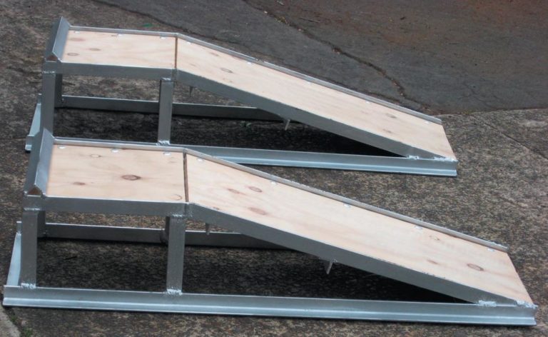
This story comes about because of a mishap with my trusty car ramps which I had for more than 20 years. They were a clever pressed-steel design, a product of Spedding Ltd, one of the country’s original importers and wholesalers who took on manufacturing as a response to the import restrictions and import licensing laws of the time.

Man of metal

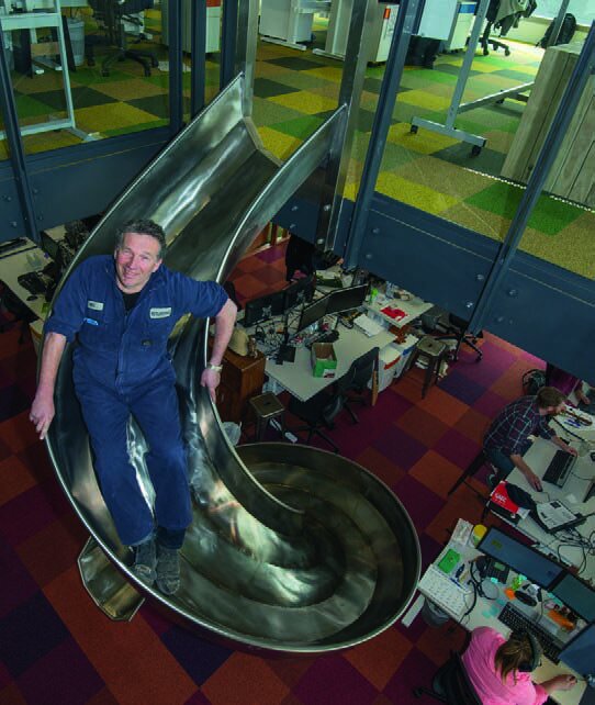
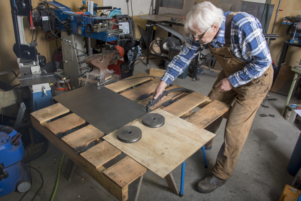
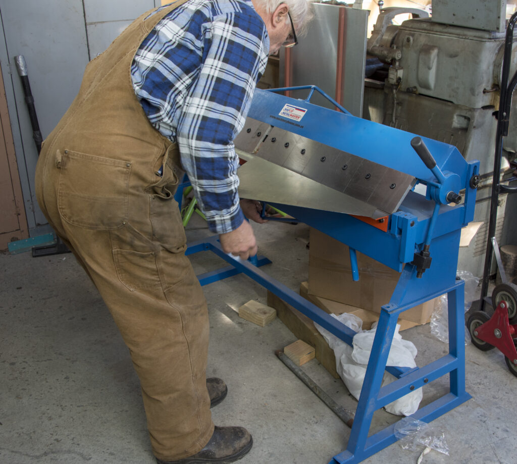
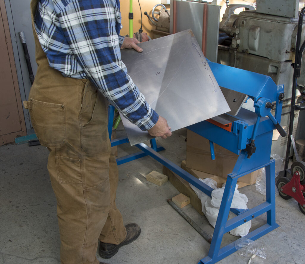
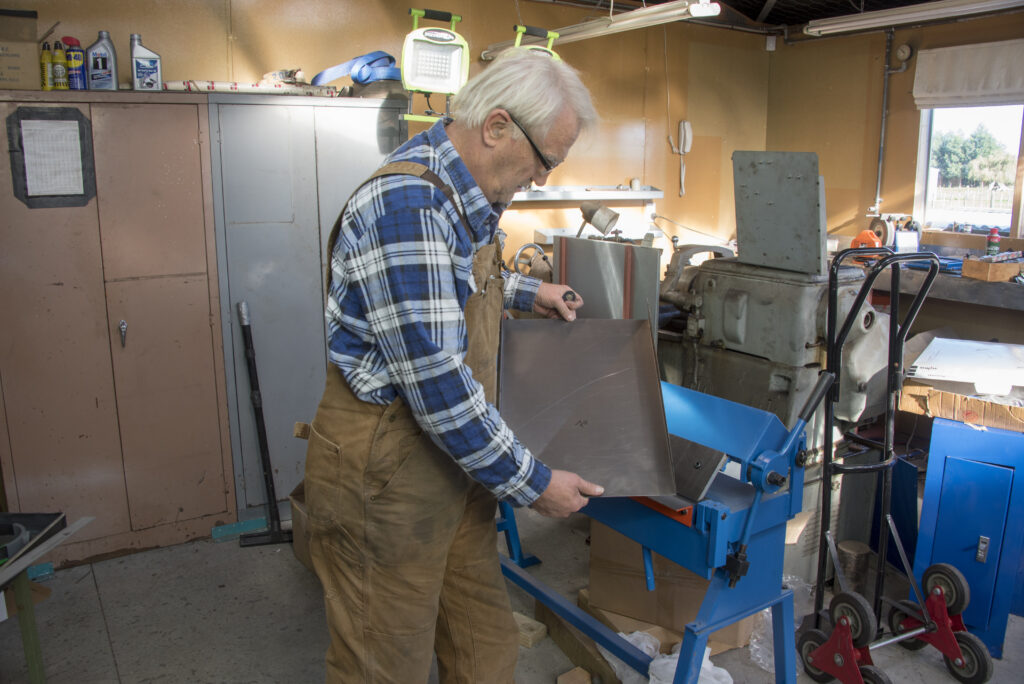
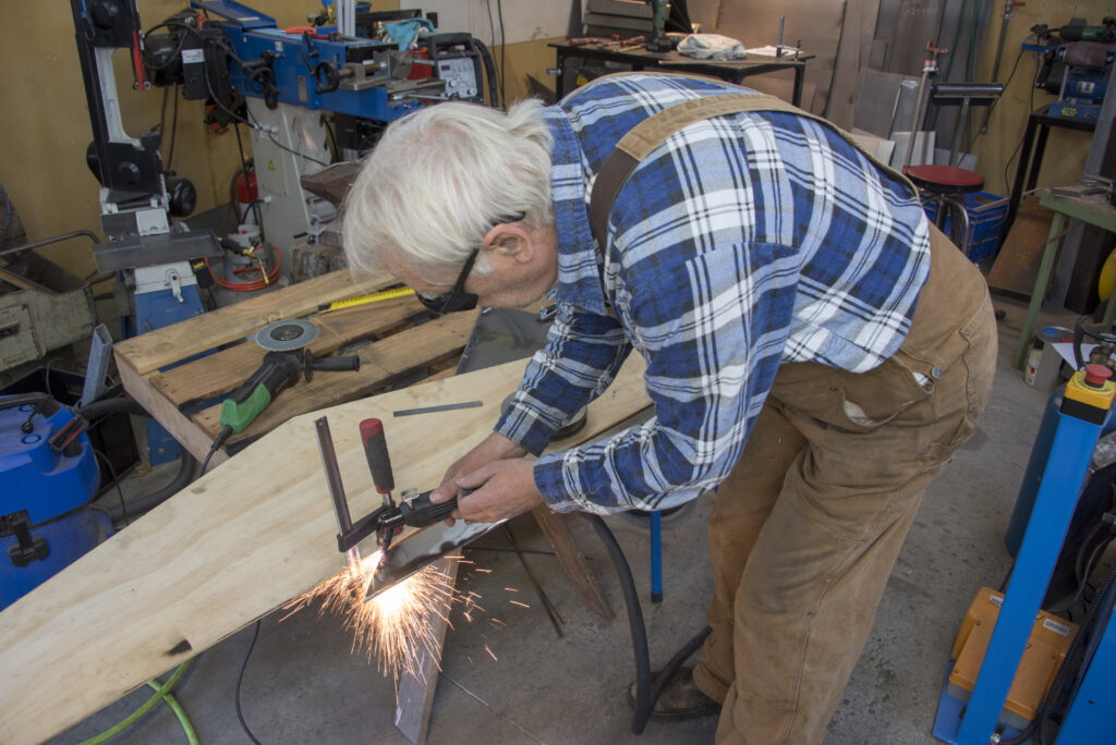
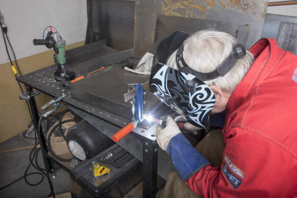
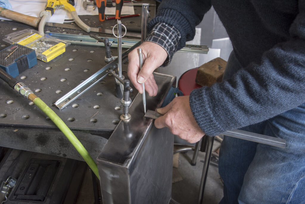
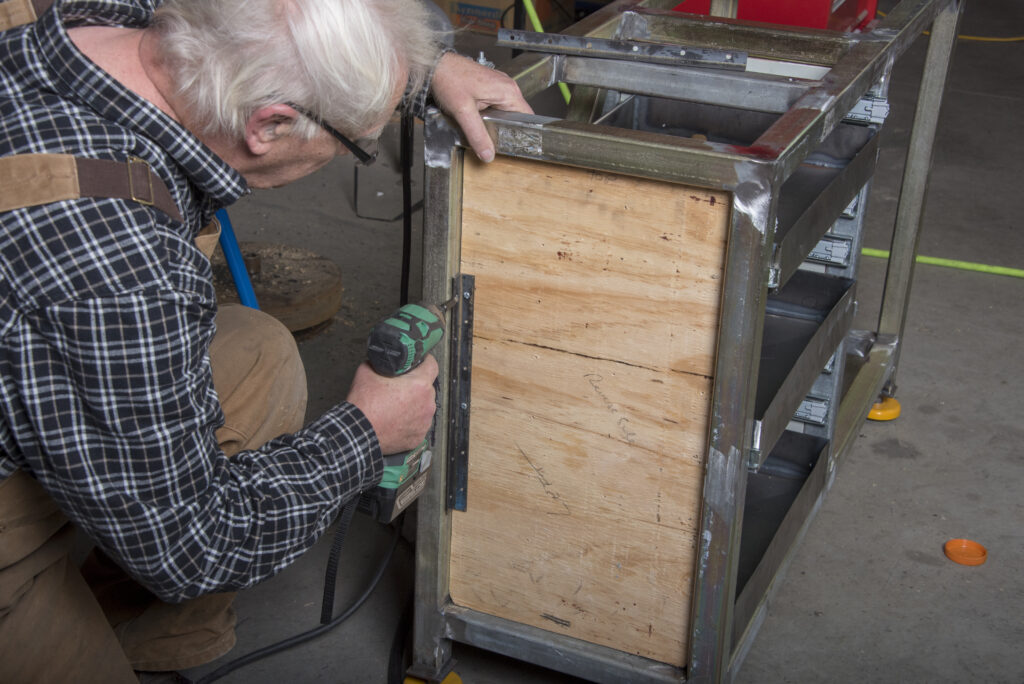
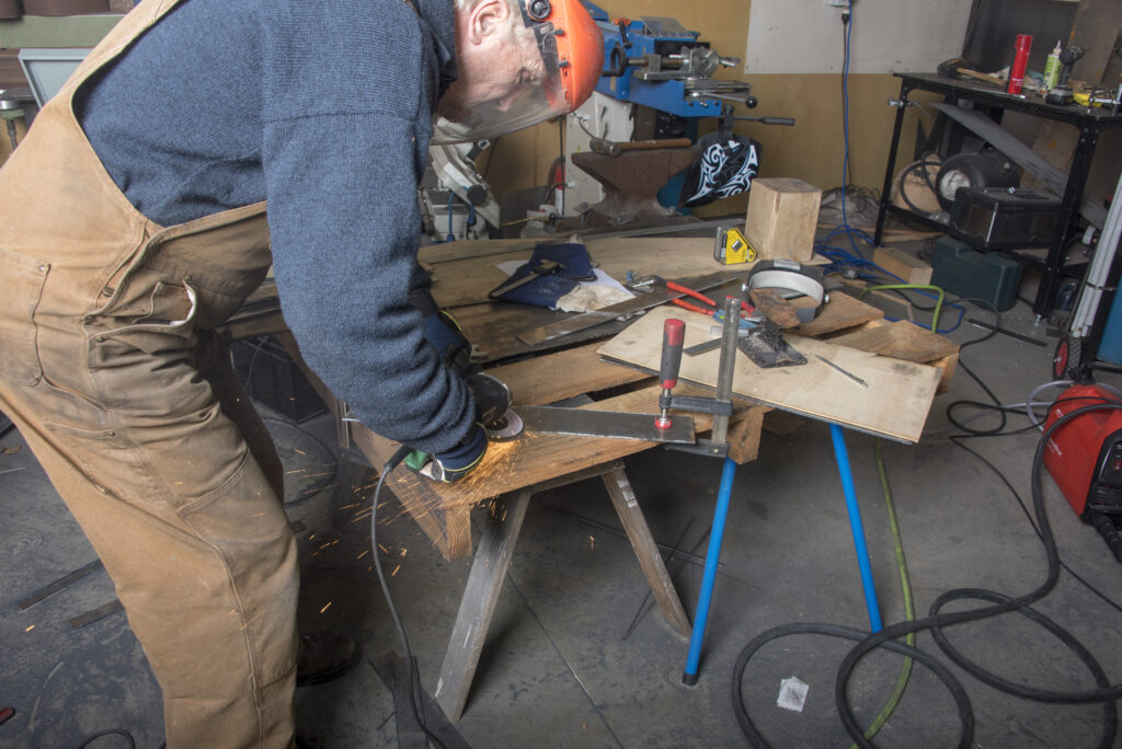
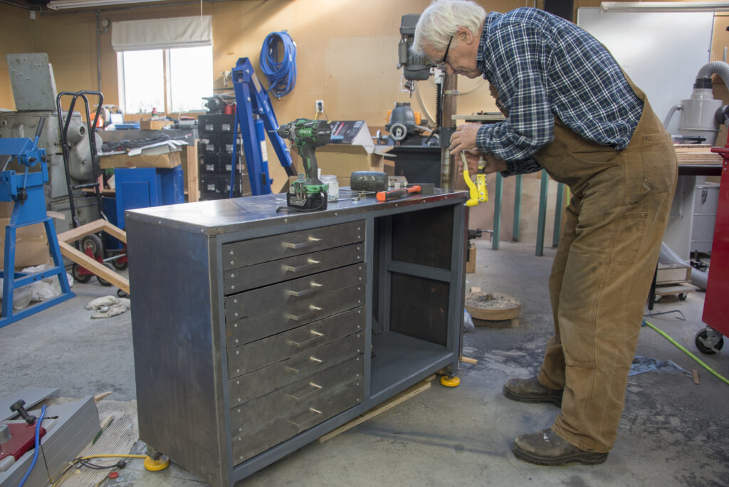
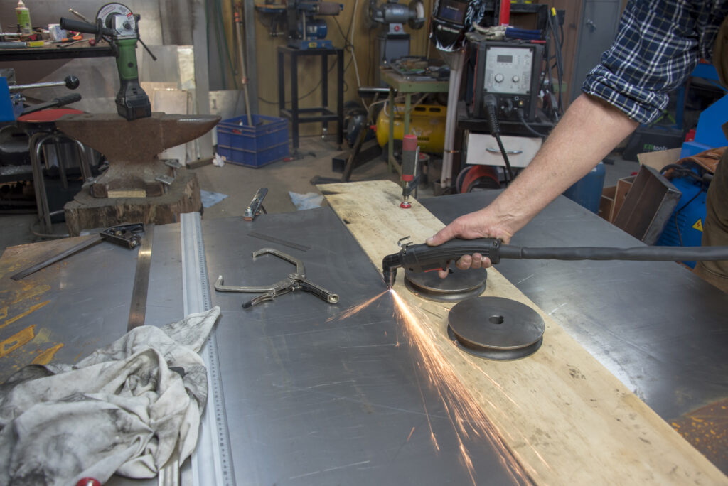
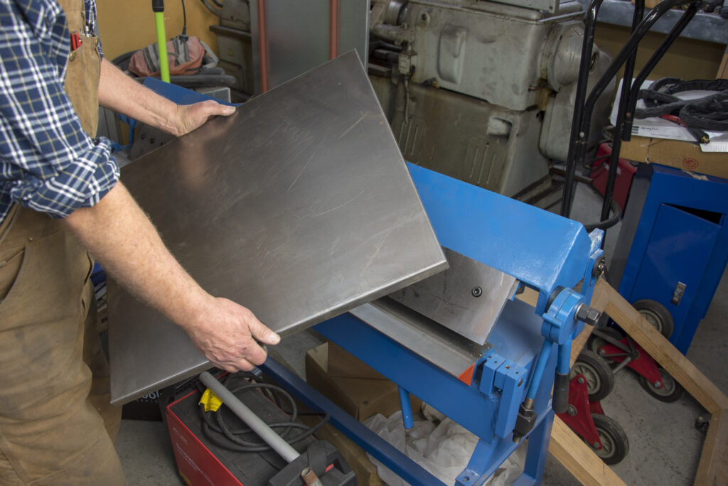
Metal is Bill Martel’s passion. He realises his own dreams in metal and those of his customers out of a very large “shed” in Plimmerton, the engine room of his business, Metalmorphic.
During 17 years of high-precision work, he and his team have made all sorts of furniture, balustrades, ornamental light shades, and more, even a 17th-century wrought iron sundial, four metres in diameter, which they “cut up into little pieces” and reassembled to correspond with the southern hemisphere.
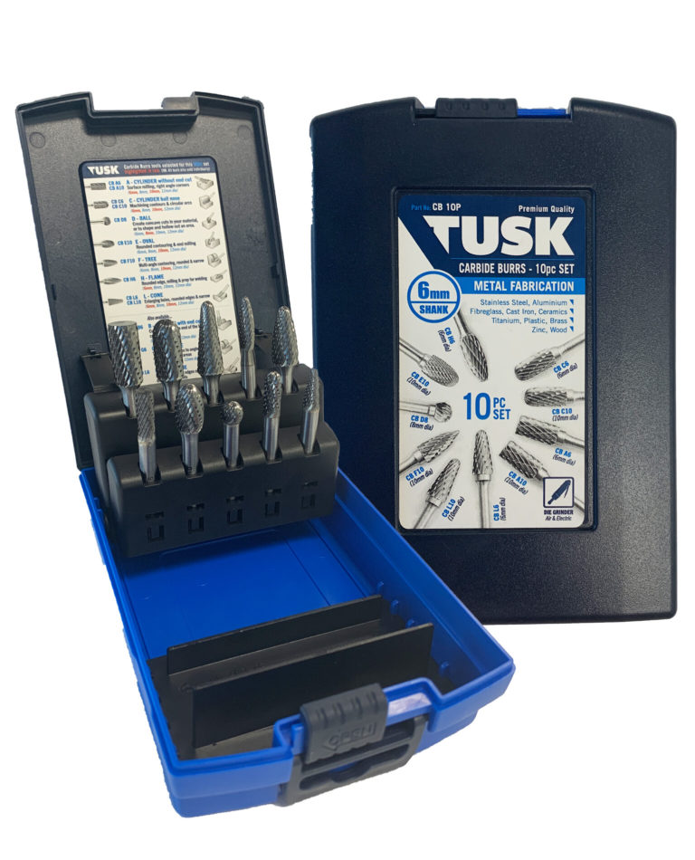