Welding: Standing to attention

I moved recently and in the haste to pack I loaded my lathe complete with its stand. The stand, which is really just a couple of sheet-metal cabinets, didn’t really survive the move all that well and it was bent out of shape. That didn’t really bother me since I have wanted to make a decent stand for the lathe since I got it, and include some drawers for tooling and other bits and pieces. Now that the lathe is in its permanent home I have my chance. This is just a small lathe but it weighs 250kg nonetheless. I wanted to make something sturdy and solid that would serve to support the lathe without sagging and eliminate any vibrations.

In part 1 of a two-part series, we commence making a lathe stand with drawers 
By Jude Woodside
Photographs: Jude Woodside

The original lathe stand – the right-hand cabinet is twisted

I moved recently, and in the haste to pack, I loaded my lathe complete with its stand. The stand, which is really just a couple of sheet-metal cabinets, didn’t really survive the move all that well and it was bent out of shape. 
That didn’t really bother me since I have wanted to make a decent stand for the lathe since I got it, and include some drawers for tooling and other bits and pieces. Now that the lathe is in its permanent home, I have my chance. This is just a small lathe but it weighs 250kg nonetheless.
I wanted to make something sturdy and solid that would serve to support the lathe without sagging and eliminate any vibrations. 

Cutting the parts of the frame
Cleaning the ends and bevelling the edges
Checking for square

My go-to tube
I still have a stack of 40mm square tube that you might have noticed I have made good use of in the past, and this is my go-to material for this job. I also want to incorporate steel drawers in the stand that will necessitate making the stand very accurately. In the past, I may have been guilty of being a touch loose in my dimensions, knowing that nothing really demanded precision, but this job has two areas that are unforgiving – the mounting holes for the lathe, and the whole cabinet being square especially where the drawers will fit.
I love the plastic nature of steel, which means you can fill holes where something isn’t quite fitting, but it does have a tendency to distort and that can be disturbing. 
I need to be quite careful with welding so I don’t apply too much heat and distort the frame. You might think I am joking that 40mm square tube x 3mm thick will distort but it does happen.

A lathe support cross member. The large hole is for access for a 17mm socket
Tacking up the frame
Tacking the first of the lathe supports

Stand design
I started with the design of the stand. I knew the position of the mounting holes and the weight of the machine. I intend to retain the tray under the lathe so I needed to make something that would match the dimensions of the cabinets. In fact, I found I could make them a bit deeper than the cabinets at 400mm. 
I wanted to incorporate four feet and machine pads that can be levelled to hopefully eliminate the tedious levelling I had to do with shims when I first installed the lathe. The cabinets didn’t have any adjustable components other than shims.

Carefully positioning the second lathe support
Tacking the second support
Welding up the top frame

Solid as
I am concerned too that the thing doesn’t rack. It is unlikely given the number of welds but I will brace the back and the ends. 
I’m not too concerned about the weight, in fact the heavier the better. I am toying with the possibility of pouring some concrete in the base too. At this stage that is just a thought.
With my basic design sorted, I began by cutting the major components to size, being very careful to make sure they were accurately sized. In fact, I ended up re-cutting a few that didn’t quite make the grade.
I started by assembling the top frame. As I have in the past, I made this with mitred joints, taking care to ensure that the ends were square and the length was precise. It’s easy to slip the mitres by a millimetre or so; that might not matter in some cases but in this instance I needed to be sure that the top frame matched the dimensions I had planned, especially the inside dimensions. 
The rolled nature of the corners on this tube make it difficult to accurately determine when the pieces are aligned to each other, so one piece isn’t lower than the one it mates to, for example. I tacked each piece and turned the whole assembly and tacked the other side too.

Cutting the feet
Drilling a foot
Tapping a foot

Access to bolts 
There are two cross members to be added to the top framework that the lathe will mount to. The mounting bolts are high-tensile M10 and currently are attached through a 1mm tray to the top of the cabinet.
I want to mount them to the 3mm-thick square section tube with the original tray and possibly another 1mm thick cover. To do that
I will need to get a socket up through the tube.
I measured and marked the holes and drilled them right through on the drill press. In hindsight, I should have used a long pilot drill first and only drilled the 10mm holes on one end. That would have made it far easier to centre the hole saw I used to cut the socket clearance hole in the other side. However, I turned the parts over and proceeded to cut the larger hole to accommodate a 17mm socket in the underside with a bi-metal holesaw. 

Welding the feet to the leg
Two above images – the profile of the Pferd fillet flap disc

Adjustable feet
I planned to put on some heavy-duty adjustable machine feet that I sourced from Machinery House. These feet screw into plates that are welded onto the legs. I cut four pieces of 50mmx4mm flat bar that I found in the scrap bin. The screws are M10 so I drilled an 8.5mm hole and tapped it. 
I have found that it is best to drill a pilot hole and then drill to the final hole size – it also saves wear and tear on your bigger twist drills. I then tapped the holes for an M10 screw at 1.5mm pitch. I stood the legs on the plates and tacked and welded each in place. 
To mount the legs to the frame I made good use of some newly acquired right-angle magswitches. They are aluminium sheathed but the magnet works well when clicked into place. The real benefit is that filings and grindings won’t stick, unlike the permanent magnet, right-angle clamps. Their extra heft made keeping the legs plumb a bit easier. I still managed to tack at least one up that was off by a couple of degrees. I managed to correct it with some judicious clamping when I welded on the bottom rail. 

Both images above – the welded foot and the weld cleaning up with the fillet disc
Setting up the leg with Magswitches

Amateur welder’s friend
It may come as a surprise to you but not all of my welds are things of beauty and it won’t have escaped your attention if you are a regular reader that I make good use of flappy discs – they are the amateur welder’s best friend. The biggest bugbear I have found with flappy discs is they don’t get into fillet welds well. 
However, I have found a disc that is especially made for fillet welds. It’s by Pferd, a German company that manufactures high-quality files and abrasives. These discs are supplied in 6mm or 8mm radius edges that make quick work of fillet welds leaving a clean, concave look.
I used them to clean up the leg welds and in fact most of the fillet welds on this project.
With the legs in place I added the bottom rails, which had been cut to 1100mm exactly, and the side rails, cut to exactly 320mm. I found it was useful to cut a couple of pieces of timber to 610mm length to help with placement. I also discovered that one of the carefully placed legs was not as plumb as I hoped and I needed to employ a clamp to take up the additional 2mm.

Welding the leg
Welding a cross member to the legs. Note the timber support
Cleaning up the fillet weld with a fillet disc

Burning scalp 
I have found after enduring too many spatters on my exposed head that it’s a good idea to wear a cap under a welding mask, but also it’s also an even better idea to clean the ends of the galvanised pieces. So I now routinely grind off the galvanised coating when I look to bevel the ends of the pieces. That makes a huge difference to the smoothness of the welding process and makes for a much tidier weld. It also dramatically reduces spatter.
I have also noticed in the past that I have been rather lazy welding vertical joints, often welding downward. That’s not a good idea – it’s far better to weld vertical up so you are not simply creating a blob of molten metal that will succumb to gravity and grow as you move the torch down to create an unsightly lump at the bottom. Welding up allows the weldment to cool as you go and you will have a better weld.

Welding the bottom rail in place
Checking the position of the middle upright with a laser rangefinder
The rangefinder is invaluable for precision measurements

Laser rangefinder 
With the bottom rails in place, I needed to add the uprights that make up the centre section. This is intended to both split the cabinet into two parts for the drawers and to help distribute the weight of the lathe. I needed something to accurately measure the space between the upright and the ends to ensure that it was equal.
It occurred to me that if my laser rangefinder would work at this short range, it would be very accurate. I already know how exact it is having used it for renovating in the past and finding it far more accurate than any tape measure, especially for awkward measurements. 
It worked. In fact, better than I thought, and it also allowed me to get the piece square.
These little digital laser rangefinders are reasonably inexpensive considering how much work you will get from them and the saving in time that an accurate measure will provide. They aren’t perfect and you have to be careful that the piece you are measuring from is aligned square to the one you are measuring to. Even then it’s possible get the odd curious measurement but in the main I have found it extremely useful. It was especially handy for centring the middle uprights. 

Marking the angles for a brace
Welding the bottom rail in place
Welding the braces in place

A bit of bracing
The two uprights are centred and welded in place. I also added the spacers between them. I noticed in doing so that the upper framework had a slight dip in the centre, so the upright in the top helped to keep the top frame parallel.
To keep the back stiff and also to help with weight, I have included two braces, also from 40x40mm stock. 
I determined their angles by the simple expedient of placing the oversize pieces in place and drawing the angle of cut with a sharpie. I was able to tack one in place while holding it, and the other I managed to clamp. They weren’t a precise fit and I did have to do a little weld build-up to fill the gap in some cases. The carcass was becoming a bit heavy and I was keen to see if there was any racking in the thing. 
So I added the feet and tested it on the floor. 
I was keen to see if the base was sturdy enough so I have test mounted the lathe to it. I was also curious to know if I needed to add the angle bracket braces I was considering adding to the ends. At this stage it doesn’t appear that I need to but I want to wait until I have added the drawers, which is the project for the next issue. There is no vibration and the stand is quite sturdy. I haven’t yet adjusted the ways for level – that will have to wait until the project is complete. 

In part two, we complete the bench, then make and install some steel drawers

Cleaning up the welds
The adjustable machine feet
Setting the lathe in place
The new stand in place

Share:

More Posts

Ramping it Up: Make a pair of ramps for home car maintenance

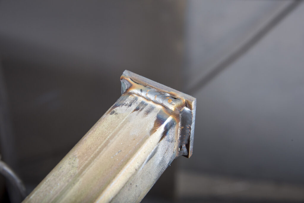
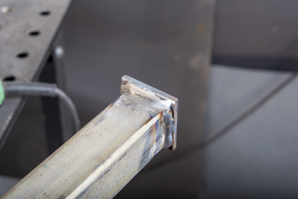
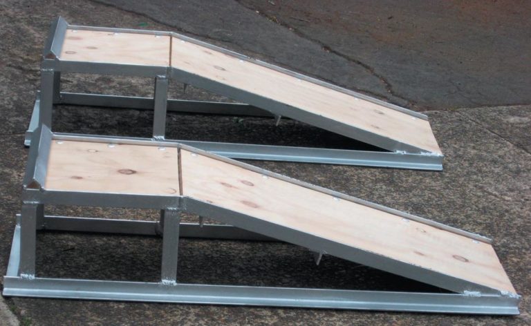
This story comes about because of a mishap with my trusty car ramps which I had for more than 20 years. They were a clever pressed-steel design, a product of Spedding Ltd, one of the country’s original importers and wholesalers who took on manufacturing as a response to the import restrictions and import licensing laws of the time.

The Shed Issue 78, May/June 2018

In The Shed issue 78, May/June 2018 we meet two Sheddies who are restoring, preserving and upgrading valve radios. We head to Whanganui to meet Graham and Val Hawtree who are avid vintage radio buffs then to Retro Radios in Dannevirke who restore valve radios bringing most into the 21st century with Bluetooth and USB upgrades.
 

Welding with LPG

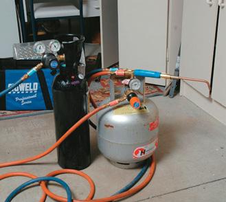
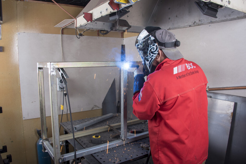
Long before MIG welders or fancy plasmas came onto the scene, the art of welding, cutting, and brazing was to work with gas. The hire or exchange cylinders used by sheddies invariably were oxy/acetylene as this was one of the most common processes for welding, cutting, or brazing.
But there is an alternative–liquefied petroleum gas (LPG) and oxygen. This combination can be used for heating, bending, brazing, soldering, silver soldering, and flame gouging to name just a few applications.