
Restoring motorbikes is what South Island sheddie Hayden Tasker loves to do in his workshop, but not just any motorbike.
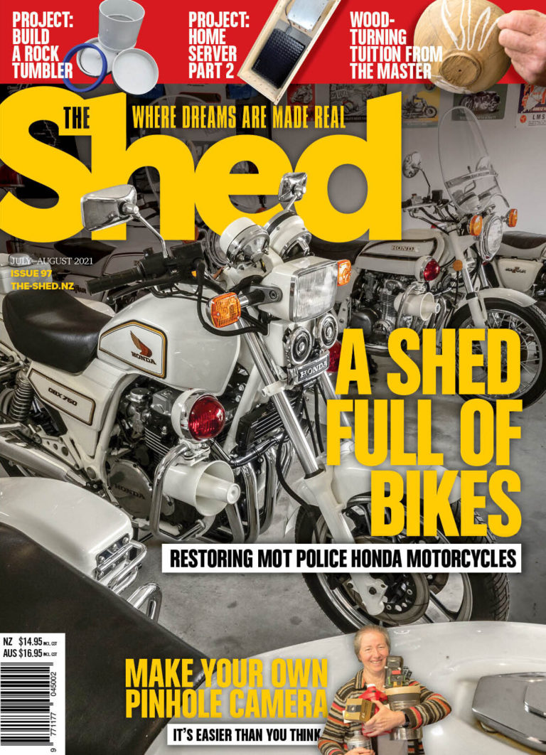
Restoring motorbikes is what South Island sheddie Hayden Tasker loves to do in his workshop, but not just any motorbike.
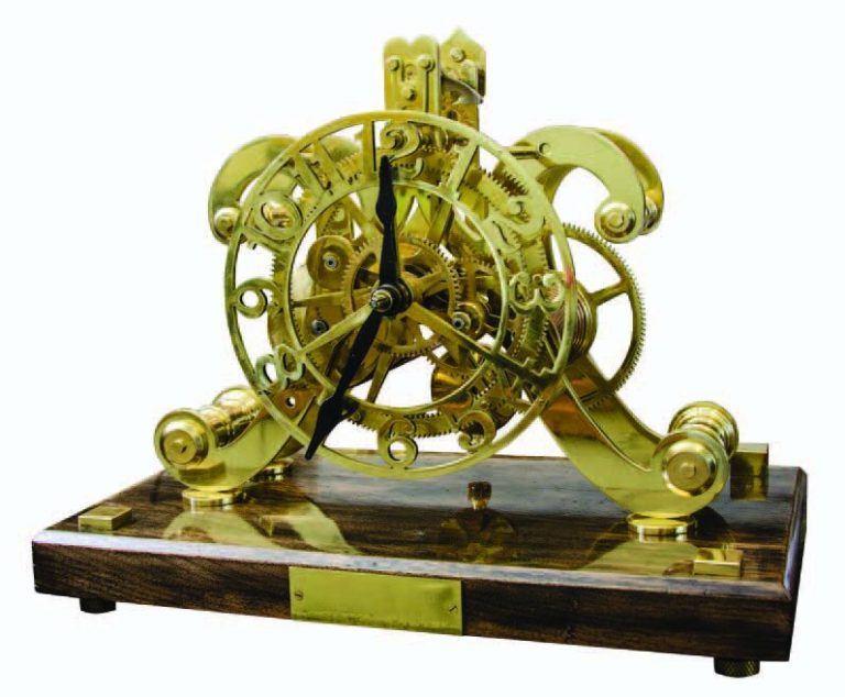
I purchased all the brass sheet and rounds required, plus a main-spring, brass bolts, and screws of the various sizes needed.
Now where to start on the clock?
I carefully read and followed the order and instructions of the book. If the instructions are not adhered to, many anxious moments and frustrations will follow.