A simple wheeled board is a great school project
By (school teacher) Ian Watson
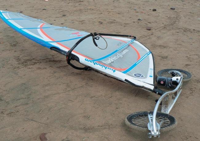
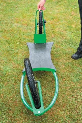
Kyle Asplin, Otumoetai College balances his dirtsurfer
Some time back my son attended a “have-a-go-day” at the Tauranga domain.
He came home so excited about a new, wheeled board thing that he had seen. He described it to me and I duly made one. It turned out to be a dirtsurfer.
He rode it for years and got quite skilled at using it. My son then left home and the board got left in a cupboard. Until recently.
One of my Year 10 (Form 4) students happened to be surfing the net and came across a site showing video of these people doing some radical things on what was called a “dirtsurfer”. He had been to all the bike shops and sports stores in town and could not buy one anywhere. Most places had not even heard of them.
I then remembered the dirtsurfer that I had made ten years ago, got it out and soon half the school wanted to ride the thing. The faster they go the easier they are to ride. Students learn to ride them in seconds.
I then came up with the idea that this would make an excellent technology project for my Year 11 class.
The real-life issue this all stemmed from was: “I wanted a dirtsurfer and I could not buy one in New Zealand. Therefore, I will have to design and make one myself.” At the same time, my students were able to record their technology practice and gain credits at NCEA Level 1.

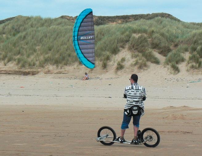
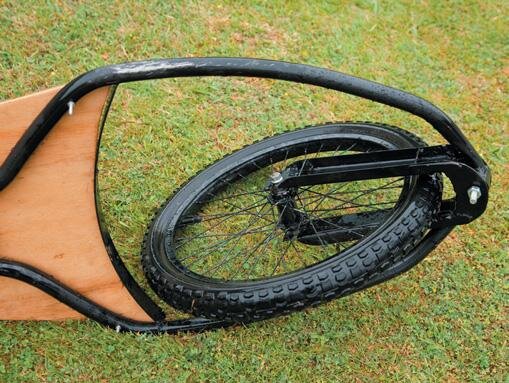
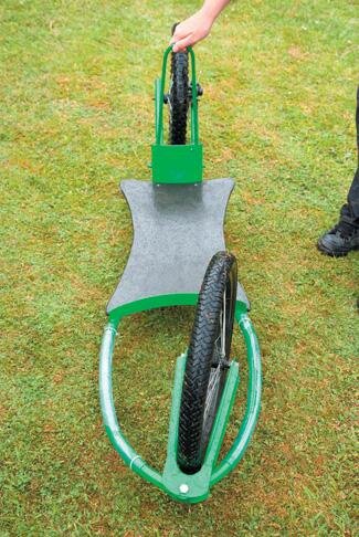
Taking the dirtsurfer across ground.
Brief
The first step was to give the class a design brief that I had written. This was really generic and included things like:
The dirtsurfer must be made in the school workshop.
The dirtsurfer must be within 20 school weeks.
The wheels must be supplied by the students.
The dirtsurfer must be made to a high quality.
The brief would be developed by the students as time went on.
The next step was to outline the most important aspects to consider when designing and building a dirt-surfer. These became our “key factors.” The class then analysed these and considered what was the most important and ranked them to the least important. The class was now ready to write the first design brief of their own. Their key factors became specifications.
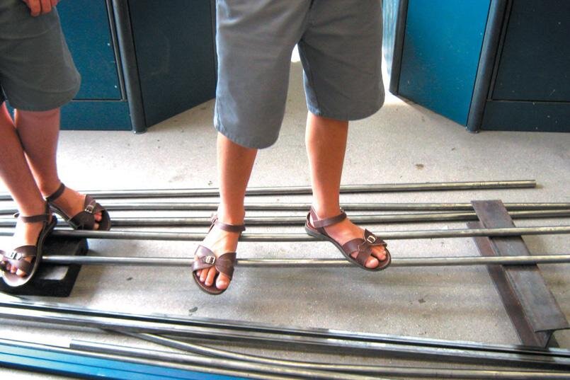
The bounce test for steel tube
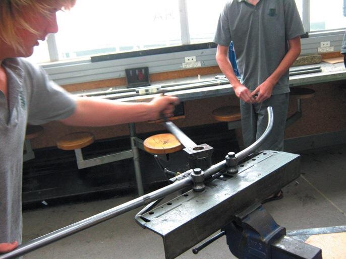
Bending the steel tube
Stakeholders
The next step was to consider all of the stakeholders for the project.
The student was the primary stakeholder as the project was for themselves, and an allowable test under the New Zealand Qualifications Authority or NZQA, the government body that does the final assessment at NCEA Level 1.
The other stakeholders were listed and their influence noted. For example, Fletcher steel was a stake-holder because they were supplying the tube. The student’s parents were also stakeholders as they were paying the bills. Then we had to produce an over-all concept for the dirtsurfer.
I have found it is impossible for my students to design an entire project at once. What I needed was an over-all concept. We would design the details as we got to each stage. The students also needed to consider the school workshop at this stage because we could only roll round tubing; any square section would have to be cut and welded.
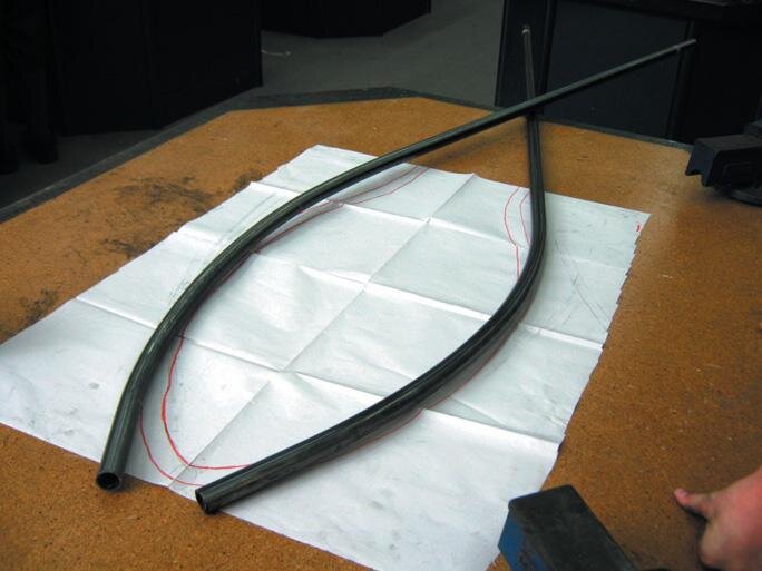
Tube checked against the full-size drawing
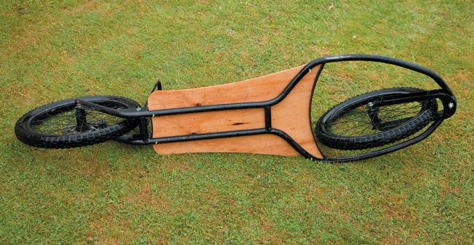
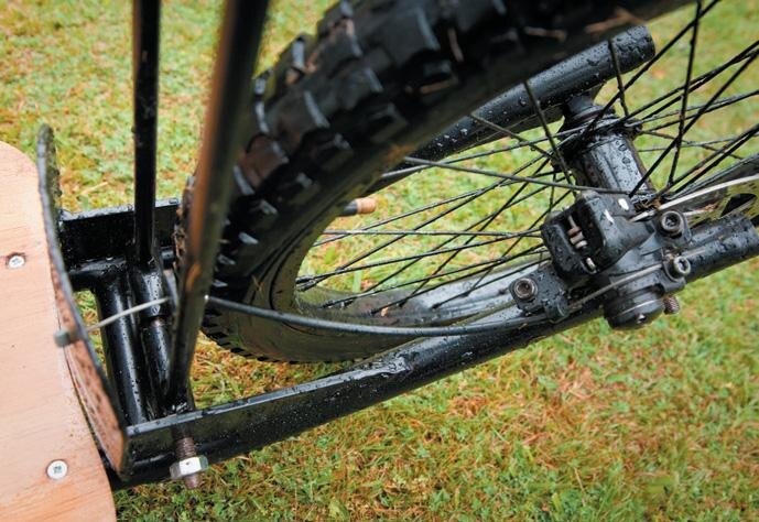
The finished frame underneath
Problem
We then got to our first problem. The students had to ask, “What size and shape of tube will I use to make my dirtsurfer?”
So that they could assess this, I ordered in every size of wall-thickness steel tube that Fletcher steel stocked in the 22 mm and 25 mm square and round section categories. The students then experimented by setting out blocks at the length of their wheelbase, putting two tubes on these and standing on them to feel the bounce the tubes would produce.
So after researching the steel catalogue, they had done a trial and test and now they made an informed decision based on their recently learned knowledge. They then re-wrote their design brief with an ex-act specification, for example, that the frame would be made of 25 mm round tube which has a wall thickness of 1.6 mm.
The next question was “What pro-file should my swing arm be?” The class went back into the classroom and we did a study on the profiles of steel beams. We looked at I-beams, C-section beams, box sections, where the stresses were, where the neutral axis was etc. They considered the folding machines the school owned and their capacity. Each swing arm was made of sheet metal that had to be cut and folded to the design of the students.
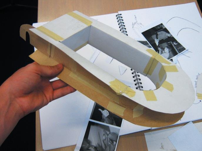
Cardboard mock-up of the swing arm
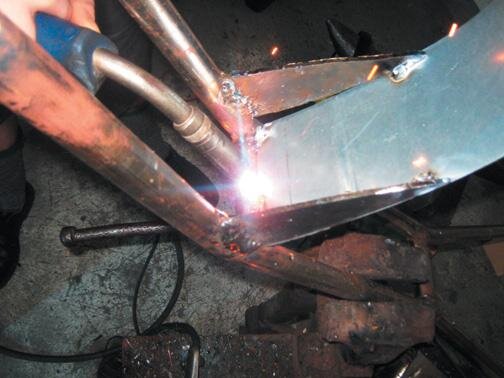
Frame being tack-welded
Swing arms
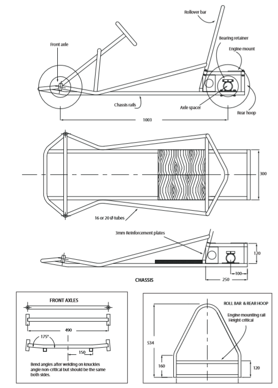
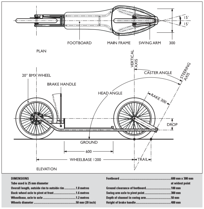
A clever part of the dirtsurfer is the front wheel “steering” mechanism.
Inside the arms of the frame at the front sits a U-shaped swing arm made of channel steel and parallel with the ground. In our case the arms of the U-shape are 200 mm long and 50 mm deep.
The back of the swing arm by the footboard holds the front-wheel axle which is fixed through the top arms of the “U”. The front end of the swingarm, the curve of the “U”, is attached to the front of the dirt-surfer frame with a vertical pin.
The pin allows the swing arm with the front wheel to pivot sideways about 15 degrees to the left or right, but not up and down, in order to steer the board. The vertical pin can be quite loose but setting it in a bearing is best. The design our students used has the vertical pin running in two bearings normally 10 or 12 mm internal diameter (ID) at the apex of the bars.
The pivot pin is tilted forward to produce a negative caster angle which makes the rider steer using bodyweight, similar to the way a skateboard or surfboard is steered. The caster angle is the angle between the vertical line which runs from the axle to the point of tyre contact with the ground and the swivel line or steering axis.
This steering axis line depends on the angle of the steering mechanism and meets the ground ahead or behind the point of tyre contact. A negative caster angle is created when the steering axis is tilted forward and meets the ground behind the wheel. A positive caster angle is the reverse.
Mock-up
To start designing their swing arms, the students did maybe three or four sketches that fitted into their overall concept. They then made a mock-up of their swing arm in cardboard to see if it looked OK (aesthetic), would fit their wheels and allow for enough steering movement (functional).
They made a further mock-up out of steel this time, to check whether the school’s equipment could do what they wanted and that the section the had chosen was going to be strong enough. The students were then able to rewrite their design brief with the required specification for their swing arm.
They made a cardboard mock-up of the axle hanger to see if it would fit inside the swing arm, hold the axle and have room to be welded in place. This became the template for the real one made of steel. Up to the point where the swing arm finally began construction, we had spent about 30 hours, shared between the workshop and the classroom as required.
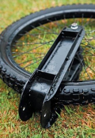
Front wheel pivots on swing arm
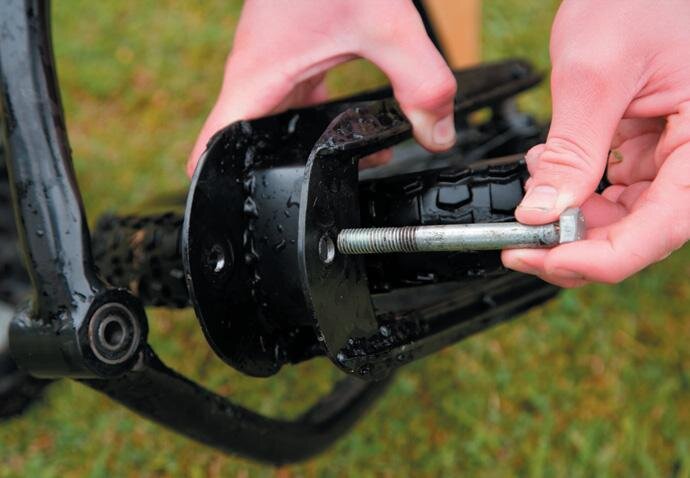
Swing arm attaches through bearing
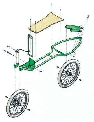
Main frame
Having built the swing arm, the students then had something concrete in which to base their design for their main frame.
The students designed the frame and produced a full-size sketch. The students then rolled the steel tube to fit their drawing. Throughout this process, unless the students had done some research of their own, as their teacher I would not give them the answer to any of their questions or let them do anything. It was common for the students to ask me a question which was met with a stony silence and them saying “You’re not going to tell me are you.”
But for 90 percent of the time, once the students had done the research they needed very little help from me at all. This is not to say that I just let them loose with the instructions “research and build it.”. One of my key areas was safety and maintenance of a high standard of work.
To mount the swing arm, the better students bored out a boss and pressed in ball bearings. Some students mounted disc brakes; some built their own braking system. The same sort of system was used for all the project i.e. state the problem, research, make a decision, evaluate and justify the decision. This was applied to every part of the dirtsurfer from the footboard shape and material, mounting, to wheel guards, toe guards, brakes, caster angle for the swing arm, finishes etc.
At the end of each lesson, the students would write in the folders of work what they did that lesson and what they planned to do in the next lesson and what resources they would need.
Brake pivot (detail).
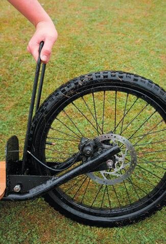
Braking system pulls on wire
Kyle reinforced the swing arm with extra welding
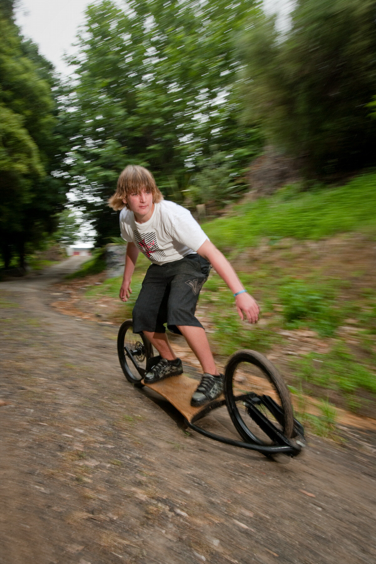
Testing
At the end of Term 3, all the class had finished the construction of their dirtsurfer.
It was now testing time. It was easy to see the students that had put in the time doing the appropriate research as their design worked a treat. The less able students who tended to just copy the research of others rather than doing it themselves were found wanting. Overall all the dirtsurfers worked. It was just that some worked better than others.
Some needed last-minute changes which showed to me that the student had not done all of his technology practice correctly. The students then wrote an evaluation of how their finished dirtsurfer met—or did not meet—the specifications of their final design brief.
They also commented on any areas that could be developed in the future. I think that my class has learnt a lot about doing things in real life, about making decisions based on what they have researched. They have solved real problems that affect their project and ultimately their final grade.
They also made a project that they like and are proud to take home. Hopefully, this not only illustrates the skills that technology students learn but also might encourage schools that may not be do-ing technology now to reconsider their stance. The expectations of students has been rationalised by NZQA. Maybe the next teacher that they employ could be a trained technology teacher and they could offer the course. Any bloke that has ever designed and made a project is a technologist and the steps they take are the same as those the students need to take, to record and submit in order to pass NCEA
Once upon a dirtsurfer
West Australian inventor Graeme Attey came up with the idea for the dirtsurfer because of a double frustration.
He likes surfing but the surf around Perth is generally small. He enjoys snowboarding, but the nearest suitable mountains are 4800 kms away. So he came up with the speedy inline board on wheels for all-year-round fun.
Attey told the ABC’s Perth edition of 7.30 Report: “What I wanted to do was just have a two-wheel device, with very low drag so it would go faster, and also turn with that same fluid motion of a surfboard or a snowboard. “It can be used anywhere from grass to bitumen to compacted dirt. You can jump it, you can do virtually all the things you do when you go skiing or snowboarding or something like that.”
The International Gravity Sports Association (IGSA), best known for skateboarding, has a section for the inline board World Cup competition.