Lessons in making a sharp, little racer
by Patrick Neal
PHOTOGRAPHS: JASON BOA, HILLMORTON SCHOOL
DRAWINGS: PATRICK NEAL
Successful class project
This is a project to build an economical go-kart designed primarily for a Year 12-13 secondary school engineering programme.
The design is not intended to be a high-performance, go-anywhere vehicle. It is a school project and therefore there are a few compromises in the design. It is economical to construct, achievable and straightforward for average Year 12 students. I might add, with some guidance.
It is also intended that most, if not all, of the Tools4work Level 2 mechanical engineering standards can be assessed against this project. Some of the techniques described may seem unnecessary, such as using a surface plate and scribing block for marking out, the design of the bearing retainers, or the generous use of a Bramley tube bender.
There are other ways to do these of course. The suggested way gives access to some Tools4work Unit Standards and makes good use of equipment generally found in a school workshop. It is designed to be safe, with an effective brake, effective steering, and good stability. Most of all the mini-kart-50cc is intended to be fun and rewarding. After all, what boy doesn’t want a go-kart?
The idea came about because my Year 11 students just were not interested in the mini-bikes being made at Year 12-13 in 2009. In the past, I had successfully built electric mini-karts powered by car starter motors, and these perform well. But the price of automotive batteries has now become prohibitive and the cheap boat roller wheels just don’t last with the wheel-spinning and drifting that electric karts are capable of.
For the same sort of money, we can build karts that are more durable, desirable, and much safer.
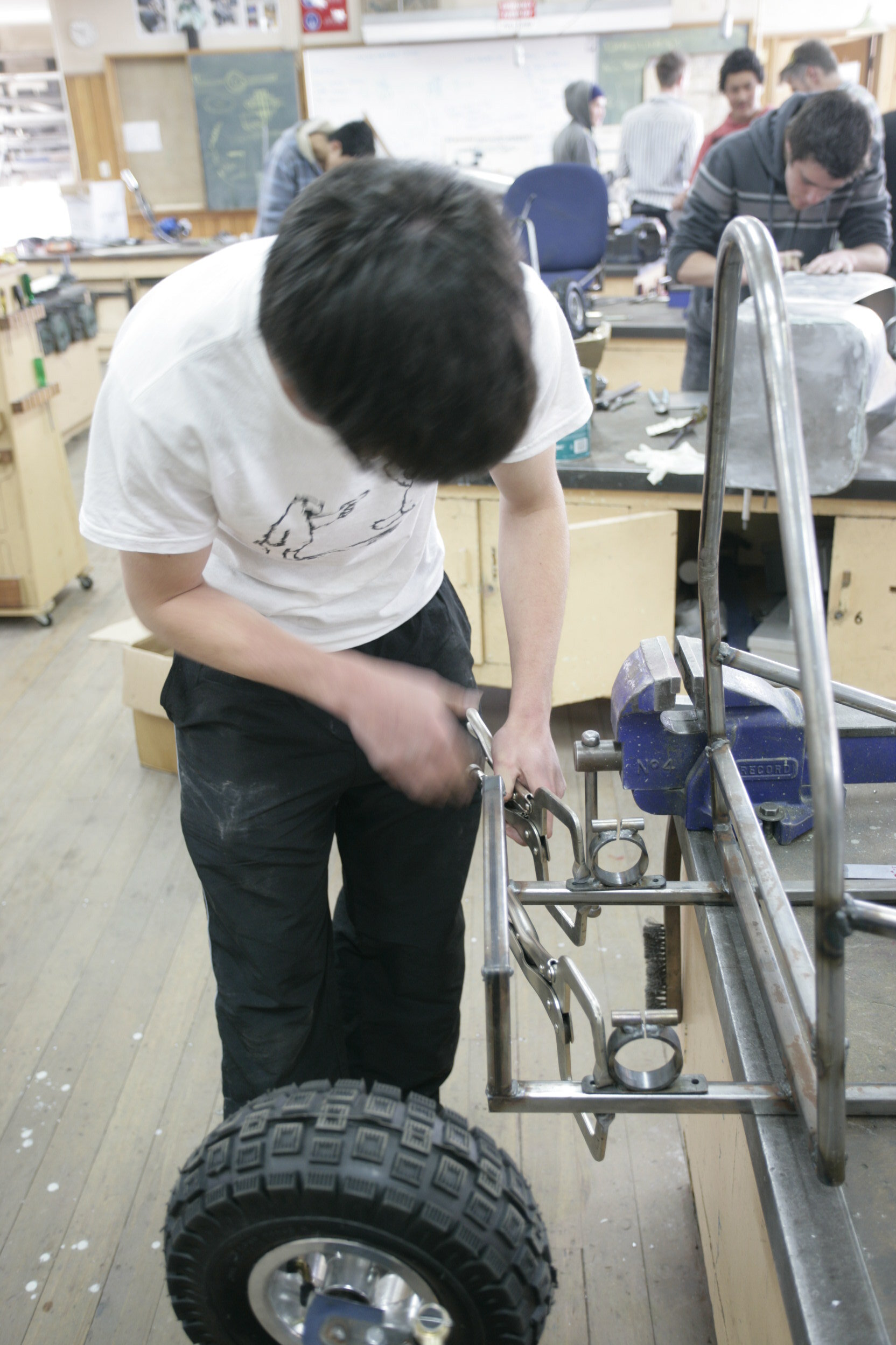
Setting up chassis on board
Kit
This go-kart is an adaptation of the 49cc Mini Quad bike kit from Newmanz RC. The cost of this parts kit [when this article was first published but currently this kit is no longer available from Newmanz RC. An online search will bring you various kit options and parts from New Zealand stores] is about $300.
Parts in this kit were an A115 engine with reduction box and exhaust Rear axle, bearings, sprocket, and chain Four wheels with pneumatic tyres Steering rod ends.
[Currently, 2020, the kit is priced at $358 but just for an engine only, and the engine specs are now a168cc 4 stroke kart complete engine kit, designed for use in Go-Karts and Grass-Karts. Chain, sprockets and clutch included. This engine is a new design and built strong. Lots of torque to pull you through the muck. The horizontal shaft is already fitted with a 420 pitch front sprocket, 420 pitch drive chain going back to a 48 tooth rear sprocket.]
Cables and fuel tank
At this stage, I am charging $120 for steel and other materials to build this go-kart. I make it clear that if any student doesn’t want to purchase the kit, their NCEA grades will not be adversely affected. Unit Standard 2387 “Mechanical assembly” is probably the only one not easily gained with-out an engine and wheels. They can, if they wish, buy a kit later.
Speed
The 50cc mini-kart does perform well with a top speed of 35-50 km/h depending on the engine.
These small engines may not have a great deal of torque, but the standard A115 engine can pull a 100 kg driver. However, in that case, the off-the-line performance is reduced noticeably compared with that for only a 30 kg driver. Modifications can easily be made to the engine to increase performance. I would suggest adding 100 mm of tube into the exhaust header length.
This has the effect of bringing the exhaust’s power-band down to a usable RPM. The standard exhausts are too short which is probably so they fi t into the bike frames. Our go-kart has no space restrictions here. The prototype now runs a standard A115 engine with a lengthened exhaust, HP carburettor and HP reeds. These economically-priced modifications make it a high-revving screamer but with noticeably more torque down low.
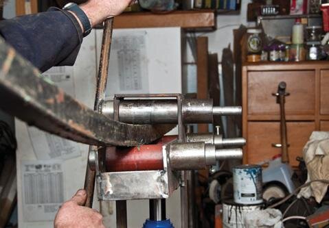
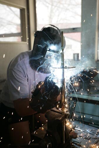
This year I started with the welding Unit Standard US 21907. The students spent the first four weeks practising various welding techniques and studying for this before project work commenced. The year ended with a bang. The boys raced the fruit of their labour at the Christchurch Kart Club’s track. It was an excellent day out and all who participated had a great time. They were well-behaved, respected the club’s premises, followed the rules and no-one was hurt. If we had another school or two to race against, the experience could have been more intense.
A few spare tyres, a puncture-repair kit and a couple of spark plugs would have also helped. The tarmac track was hard on the tyres, so maybe a grass track next time? The chassis holds all components in place relative to each other and gives a comfortable place for the driver. It should be simple to construct and be fairly rigid. The design is constructed from square and round 20mm x 1.6 mm ERW (electric resistance-welded steel) or “furniture” tube.
The driver’s seat is integral to the design with seat, back and side-rails forming a stiff triangulated structure. The chassis is fairly straightforward and should be assembled on a piece of MDF to ensure it is straight in all planes. Draw a datum down the centre of the board and take all measurements off this.
The tolerance is +/- 10 mm, which should be easy to achieve but you should endeavour to make it much more accurate. Use the drawing to position the two chassis rails, marking two parallel lines off-set 150 mm to the datum. Make the chassis rails by bending them in a square tube-bender. The angle is not critical, but it is important that the two rails are close to identical. It is also important these rails are welded in parallel. Use a roofing square to mark perpendicular lines to the datum to represent the rear hoop rectangle and oval roll bar positions.
The rear hoop is at the far rear and the roll bar is 250 mm from the rear. The front axle can also be marked out although the measurement for this is non-critical. It should be placed forward of the chassis rail bends. Placing the axle here on the angle gives the steering caster or self-centring.
Rollbar
Next, draw the rollbar out on a piece of MDF or cardboard.
Use this drawing to help bend the shape. It is suggested you cut the tube longer than is required and form the middle bend first, then the two other side bends. Next, make the front axle.
The bends can be made either before or after the knuckles are fitted. I weld on the knuckles, ensuring they are square, then bend the axle tube in the tube bender. The angle is not highly critical but both bends should be the same and positioned 150 mm either side of the middle. Again, mark the middle, so as to position it over the datum line of the MDF board. Make the rear hoop now. Using a combination square, mark the birds-mouth cut-outs.
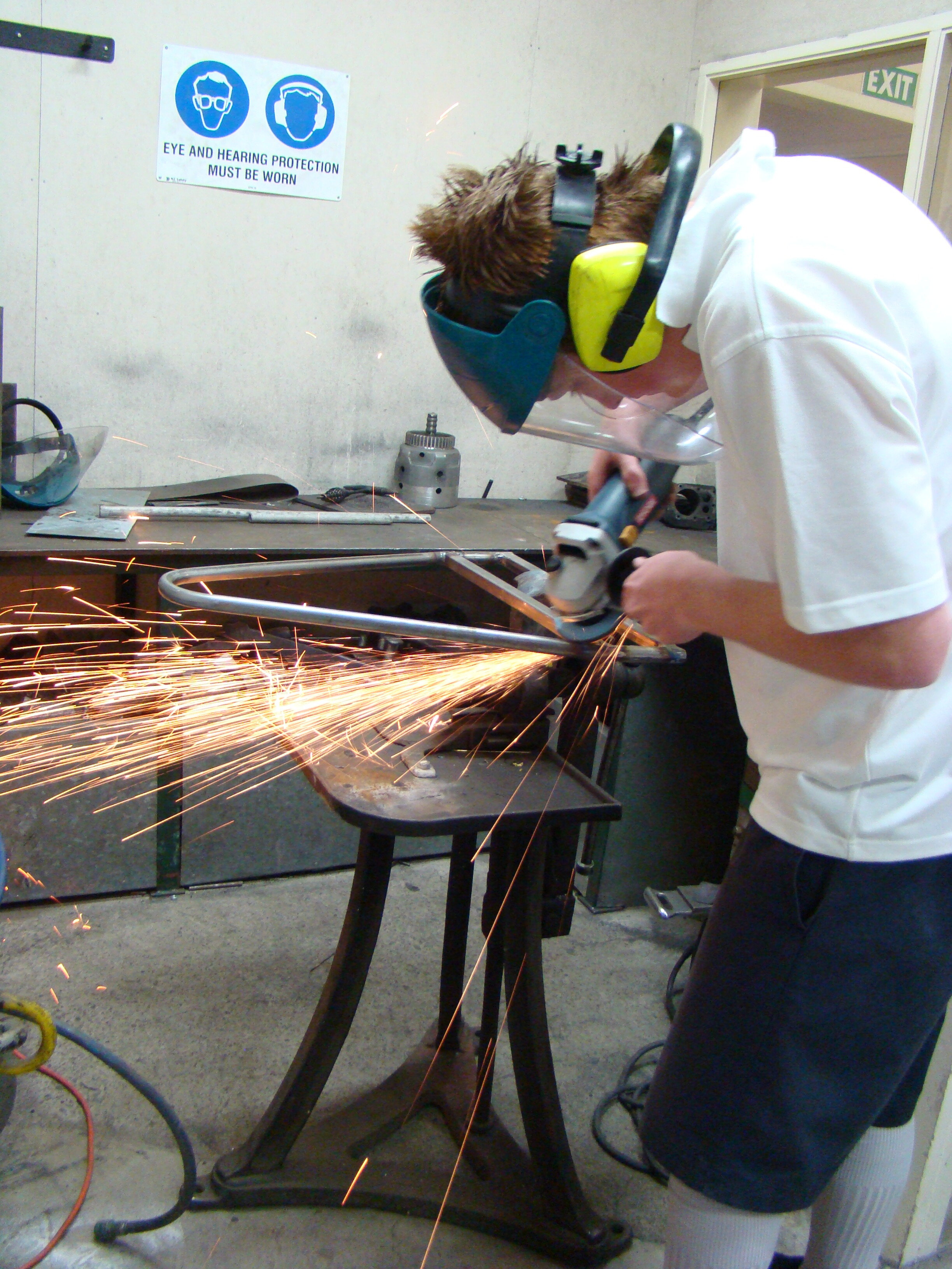
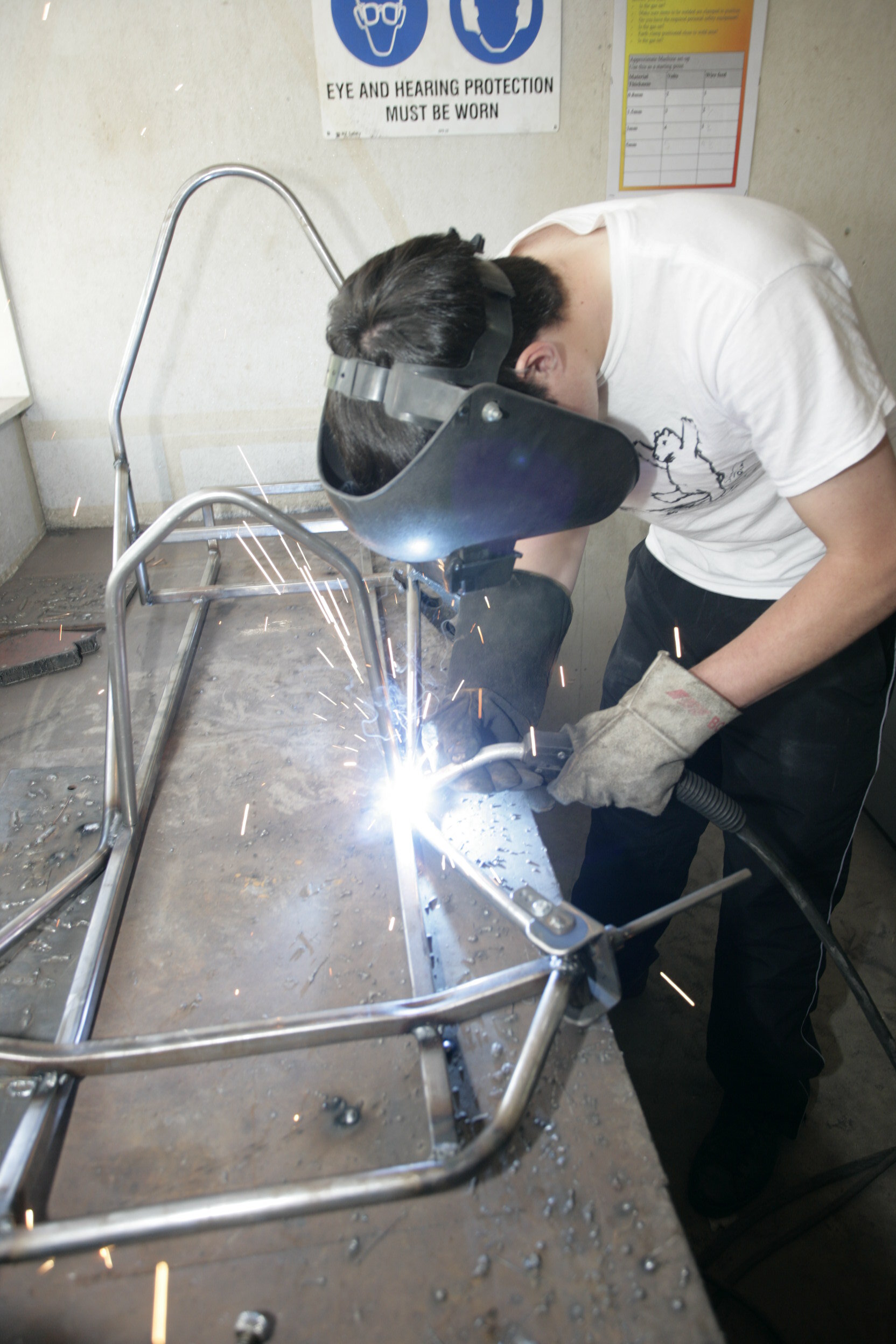
Cut the birds-mouths on the generous side to ensure the sides bend down properly. Tack this frame to hold the 90-degree angles. Now it is time to assemble the frame. Position the chassis rails over your MDF chassis drawing and clamp them down. Add the roll bar, rear hoop, and front axle, clamping these in position. Ensure the centre lines on these parts are positioned over the datum line.
Without loosening the clamps, you can tap the parts gently with a hammer to get them positioned accurately. Tack-weld the chassis together. Don’t fully weld it yet as some parts might need moving. The front and side support tubes can now be fitted.
These tubes add considerable stiffness to the frame and support for the front axle so they should not be neglected. They can be made from 16 mm or 20 mm round tube. The side tubes are attached to the roll bar at either side and run at an angle down to the chassis rails. There they are welded before continuing onto the knuckles. The side tubes are shown as one piece with a bend. This is not entirely necessary as they could be made in two parts although the one-piece design looks tidier. Once the steering components are made, you can design a suitable steering column and wheel. Make sure the column supports are robust and triangulated. You don’t want to have your steering column let go when you are cornering at speed.
Attach disc brake wheel
Placing split cylindrical housing for bearings
Bearing retainers
The supplied rear-axle bearings come in an eccentric housing which allows some chain adjustment.
You need to make a cylindrical housing for the bearings which is split so it can be pinched to clamp the supplied, alloy concentric bearings. A mounting plate and a boss to support the pinch bolt are welded to this housing.
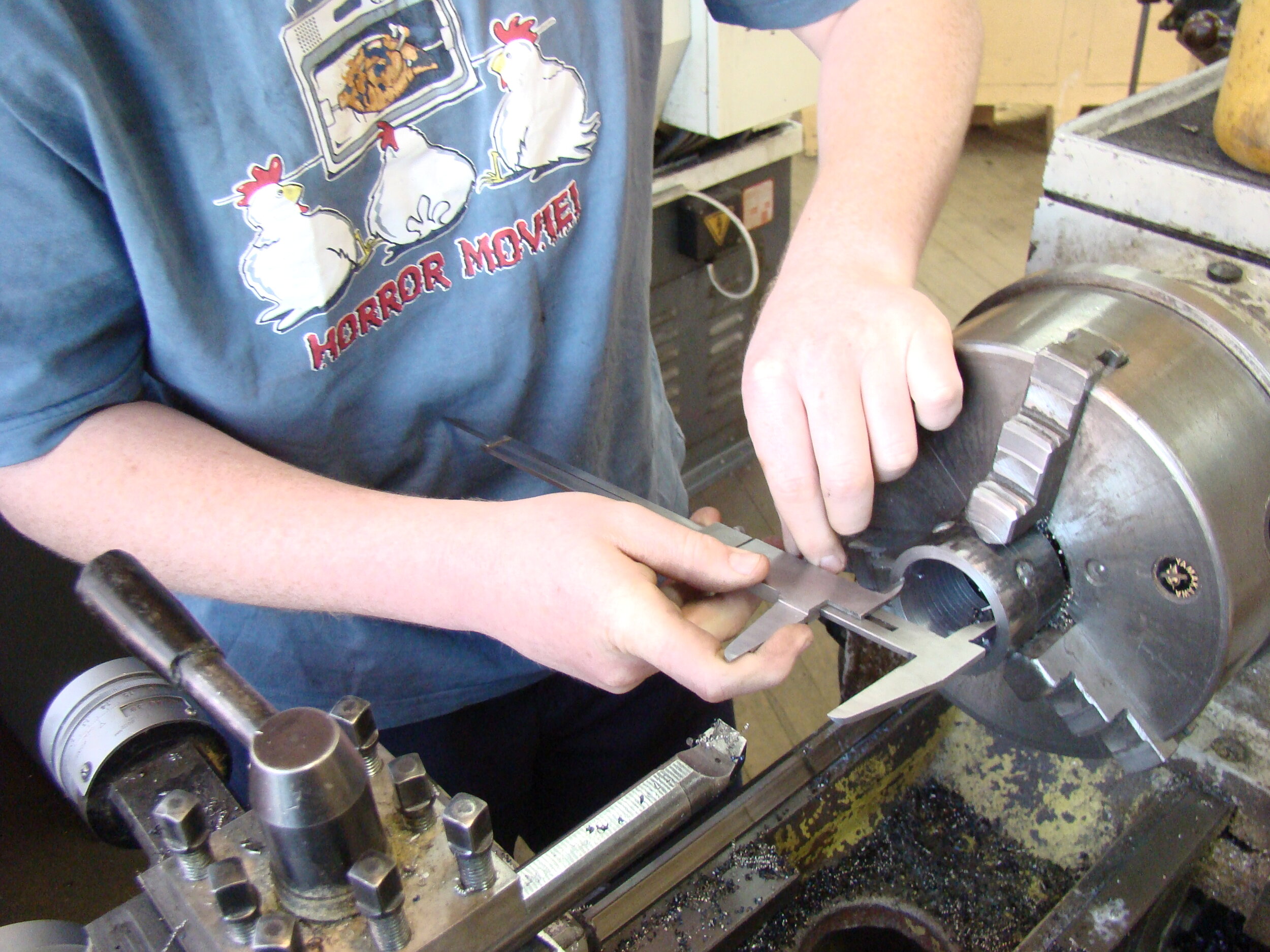
To make the rear-axle bearing retainers, cut two pieces of hollow bar slightly oversize. On the lathe, face these to the width shown. Tack-weld both pieces together to ensure they are aligned then, on the lathe, bore out these parts to size. Note the tolerance of +/-0.1 mm. Once they are bored to size, you can separate the two retainers.
Now make the two 12 mm diameter bosses at 50 mm long with a 6 mm clearance hole. Make the mounting flange from 20 x 4 mm steel. Hold all parts together in a vice to ensure they are parallel, tack-weld, check, and then weld securely with a generous fillet. Use an angle grinder and cut-off disc to make the slot in the retainer. This slot is there so the retainer can clamp onto the rear axle bearings. These retainers can be fitted to the lower rails with M6 bolts and Nyloc nuts.
Steering
The steering design works effectively with caster, camber, kingpin inclination, and Ackermann steering geometry built in to ensure good steering response and self-centering.
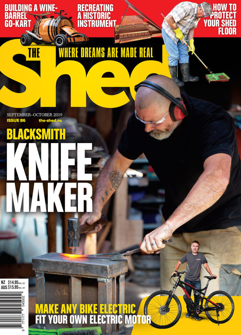
The prototype steering-column configuration with the early kits used a set of handlebars and column. Most of the boys have simply fabricated a steering wheel using the Bramley tube bender. The wheel is made in two 180º bends from 19 or 20 mm ERW tube.
The trick here is to use the Bramley’s 20 square-tube bending former, not the round one, as it has a larger bend radius, making for a good wheel size. The steering components should be fairly straightforward. Make the steering uprights from 75 x 50 mm RHS. We marked them out using a surface plate/table, a scribing block and dividers to access some Tools4work Unit Standards. Once they are marked, drill holes and then cut the section marked out to make a C channel. Finish by rounding the radii on the top and bottom.
Bolt these to your chassis and using a power drill and 10 mm bit, realign the 10 mm axle holes to horizontal. The 10 mm axles can now be placed in, ensure they are absolutely horizontal before welding. Weld securely on the inside with the MIG set hot to ensure good penetration. Weld the outside with a tidy fillet and then slip the stub axle sleeve over this weld. Weld this sleeve on, but only around the outside with a generous fillet.
Do not weld the sleeve onto the stub axle as this face needs to be accurate because the wheel bearing rests up against it. Note the kingpin configuration—you will see that the kingpin is welded to the steering arm. This ensures the kingpin rotates with the upright when the steering is turned. This produces less wear on the kingpin and on the upright than if the kingpin was al-lowed to float.
The steering arms have two sets of rod end holes, giving some adjustability to the feel of the steering.
Teacher Patrick Neal assesses steering wheel position.
Attaching steering plate.
Steering tie rods
The tie rods that come with the kit are now too short.
We have widened the track of the mini quad rear axle, so we have to do the same here. There are two options. The simplest is to cut the tie rods then weld on a sleeve to widen them. The other option is to thread on a piece of 8 mm rod. We purchased a left-hand M8 die which cost us over $60. When cutting the rods to length, make sure there is plenty of rod screwed into the rod ends, but not enough for it to bottom out, restricting the toe adjustment.
Left-hand die cuts tie rod thread.
Setting new tie rod in place
Attaching seat back to roll bar
Steering assembly.
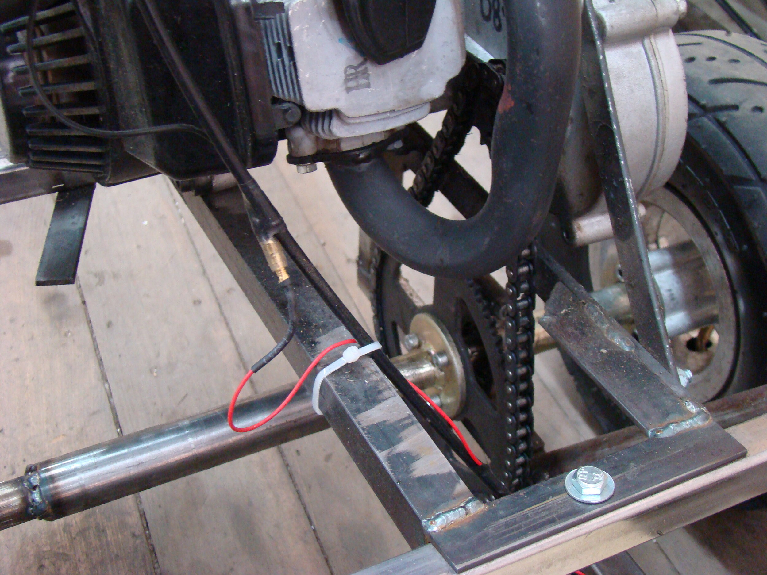
Engine mount
The engine mount is a cradle that is designed to slide from side to side to allow chain alignment. It was also designed to allow other (bigger) engines to be installed with other cradles at a later date. The mount is made of 3 mm mild steel and constructed to fit snugly between the rear hoop and the engine-mounting rail on the roll bar. It is a good idea to use countersunk cap screws. Note the metal-bar brace attached to the top of the reduction box from the engine mount below.
Do not neglect to install this as it reduces flexing in the engine mount.
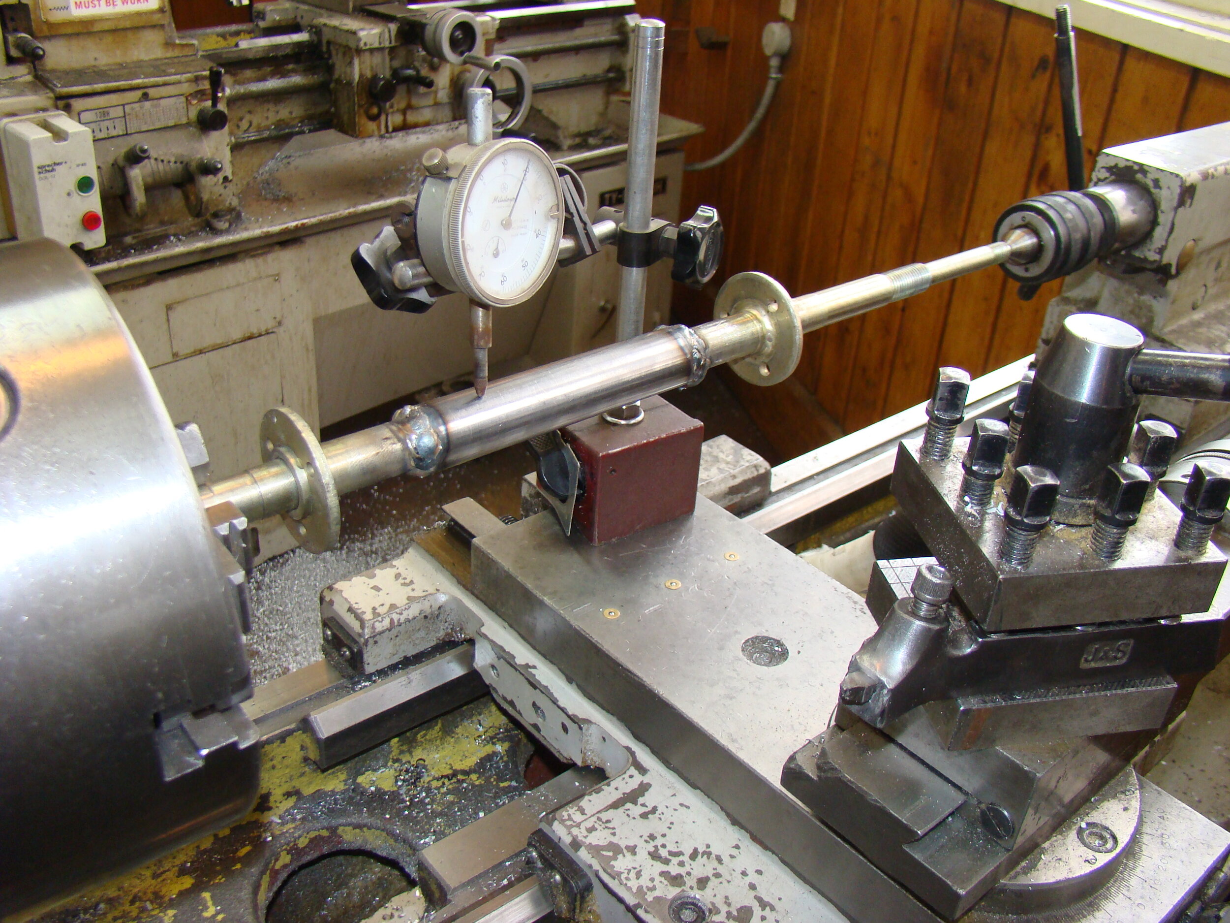
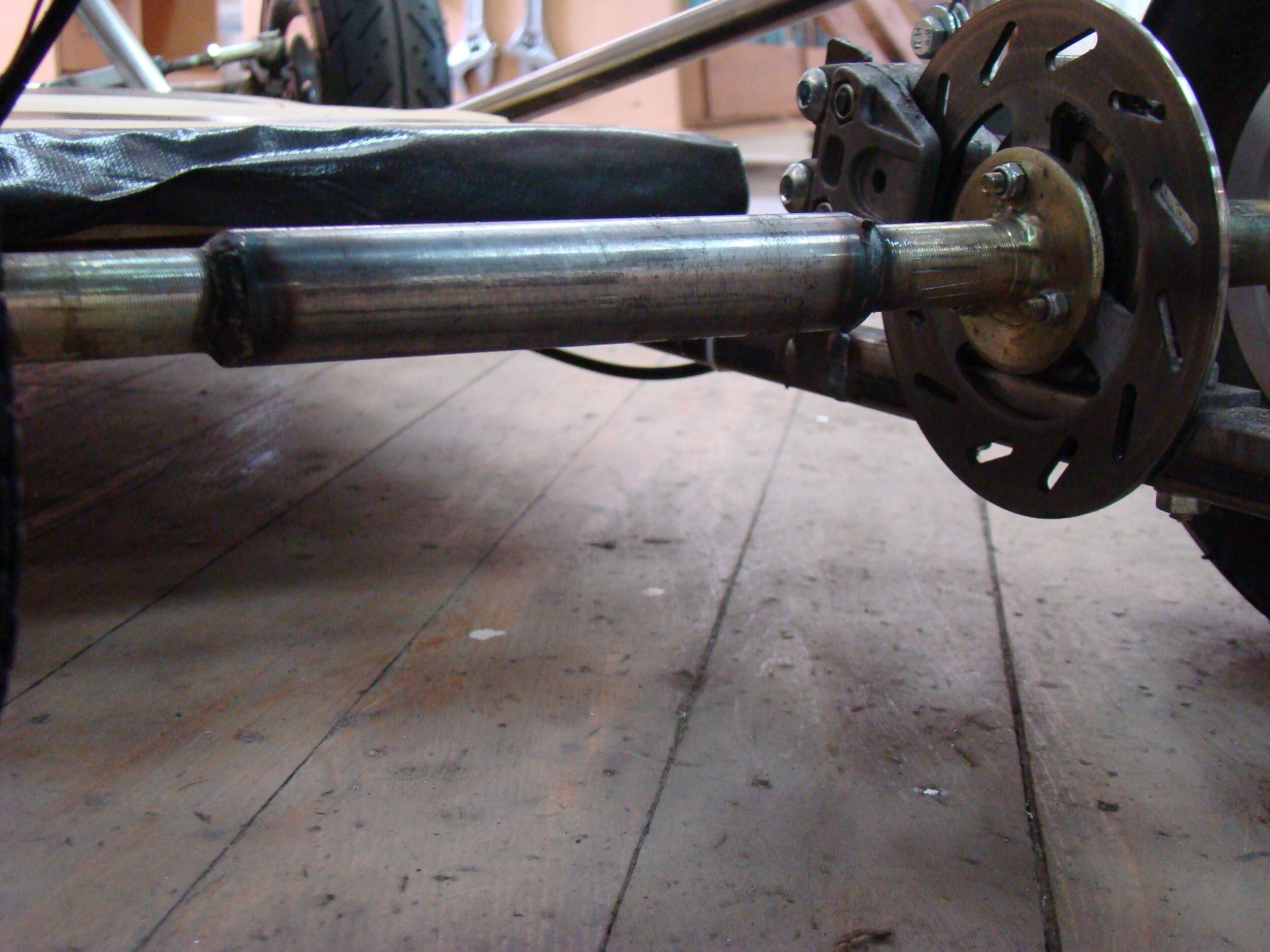
Rear-axle spacer
This mini quad is a small machine designed for a child so the supplied mini quad-axle is too narrow for our go-kart and needs widening.
The technique is to cut the axle in half, then turn up a sleeve from 25 mm-diameter mild steel. Cut your axle and assemble it onto the bearings. You will need to make the spacer with deep enough holes to allow the axle to sit properly in the bearings. Tack the spacer to the axle in three places with a MIG welder set hot.
Put the axle into a lathe between cen-tres and straighten to ensure it runs with minimal run-out. I have found it best to do this in two stages. Hold the spacer in the chuck and align one side of the axle to it. When you are welding, set the MIG hot to ensure good penetration. Repeat with the other side. When welding is finished, re-check run-out on the lathe.
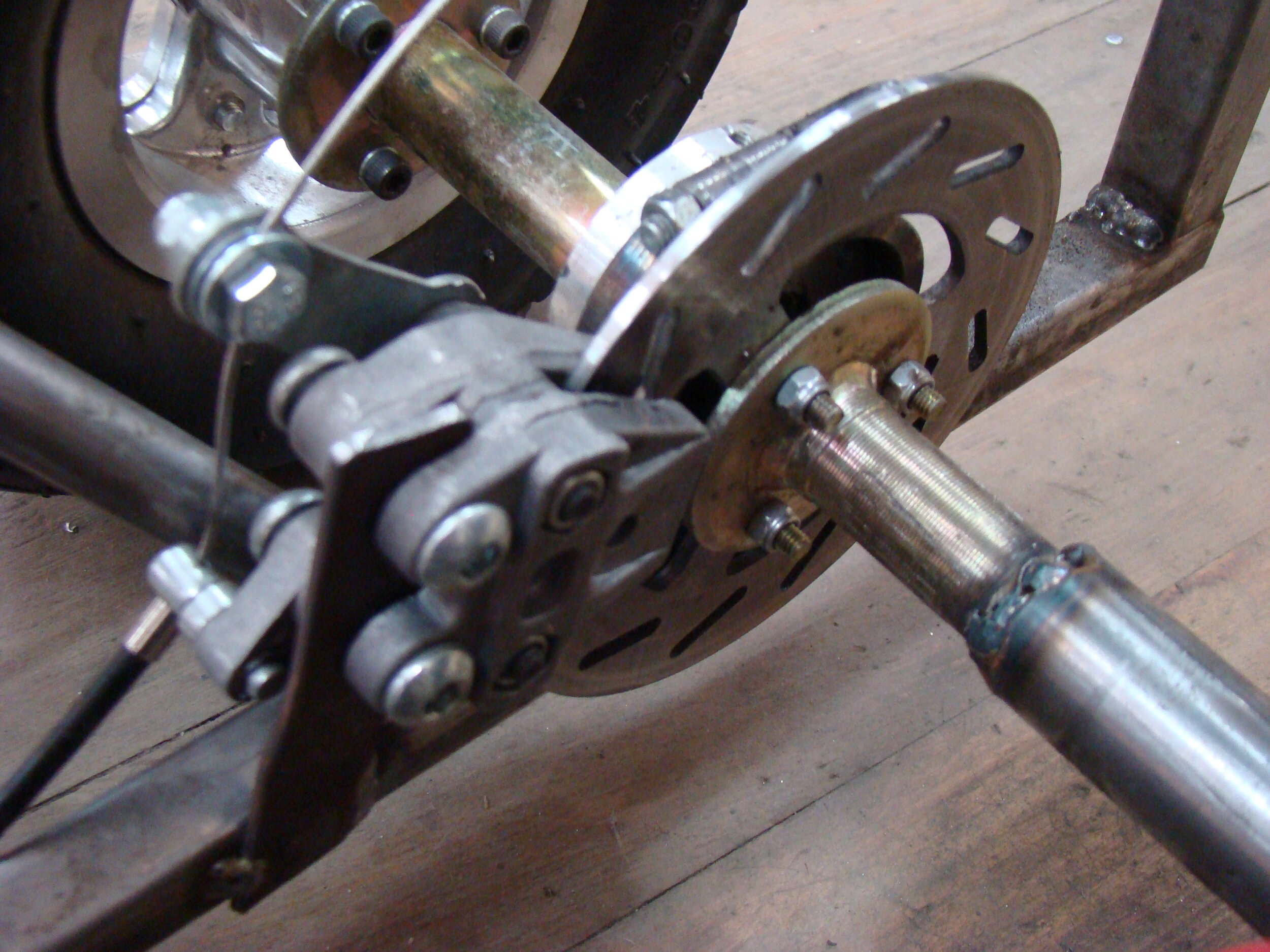
Disc brake calliper
The kit comes with a single disc and calliper actuated by cable.
The brakes are quite effective, although, there is no back-up if the set-up fails. The calliper can simply be mounted onto a piece of 20 x 3 mm steel. Special bolts are included so the calliper can fl oat a few millimetres from side to side. With the axle home, make sure the calliper sits centrally over the disc with the maximum amount of pad in contact with the disc. Note the disc is held in place with Nyloc nuts. You’ll be surprised what vibrates loose.
Helping hand with pit repairs
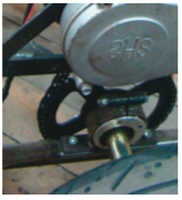
Trouble with the drive wheel.
Cables
The 1.2 metre cables supplied in the kit are too short and this caused a few headaches.
I hope Newmanz will supply two-metre long cables next year. You can buy two-metre cables from a bike shop, but be aware with bike cables that the throttle cable needs a small nipple added to the carburettor end to engage in the carburettor’s piston.
Other bits
The steering column, pedals, seat and fuel tank are open to the individual and I have not included any drawings for these. I use Unit Standard 2430 “Draw and interpret engineering sketches.” In this standard, students learn to interpret my orthographic drawings; they convert these into 3-D sketches and then produce their own orthographic drawings of their designs. There are no credits for design, just their final idea on paper and in steel.
A finished kart
EXHAUST MODIFICATION
You can do the math if you wish.
The exhaust port is open for 150º of crank duration and the exhaust wave velocity is around 1400 ft (426 metres) /sec. The effective length of a tuned exhaust is measured from the piston face around any bends to the reflective point of the rear cone.
The reflective point is close enough to half the cone’s length. Double this length, as the exhaust pressure wave has to bounce back, travelling back and entering the closing port just before closing.