On a tipping trailer, the hydraulics do the hard work
By Ray Nielsen
When I first looked at building a tipping trailer, I wondered whether I would be building a trailer with a hydraulic cylinder under it, or fitting a hydraulic cylinder under a trailer. After due consideration, I realised that a trailer is a trailer, regardless of the frills.
I therefore decided to reproduce the trailer built by Tony Cullen in an earlier issue of The Shed magazine. This is an excellent, 1800 mm x 1200 mm (6 x 4 domestic) general-purpose, single-axle trailer and certainly within the realms of any home engineer with welding skills. I would then add some hydraulics and, by the miracles of modern science, I would have a tipping trailer.
Anyone who has already built Tony Cullen’s trailer can easily convert it to our tipping trailer. The main change is to add a sub-frame to accommodate the tipping components: cut away the spring carriers and the drawbar and then fabricate the sub-frame as covered later in this article.
Anything welded underneath this frame, such as guard brackets, will have to be removed or cleared be-cause these bearers are going to be sitting on top of the new subframe. I have also changed the light and number plate bar at the back, mainly to get my hinges as far back as possible. I also find with any tip-per there is a tendency to back the trailer over things with the deck up and the first casualties are the lights. So I like to have them out of the way at the back.
To start building the trailer, I set up on a nice flat area where I could work easily without tripping over everything as work progressed. I had two large off-cuts of 150 mm x 100 mm rectangular hollow section (RHS) steel which I used as my working base. I know they are dead flat and true, and I can put my welding earth strap on one of these which saves me shifting my earth every time I want to weld another component.
Bottom mount
Tacking
Next, cut out and set up the main trailer frame. Sit the four, 40 mm x 40 mm x 3 mm sections on your working platform and roughly square up. Put light weld tacks in every corner to hold everything to-gether, and then do the final squar-ing using the diagonal method. It’s much easier if you have someone helping but if you are by yourself, the steel working platform comes in very handy here. If the frame keeps moving, and you are strug-gling to get it square, put a couple of tacks onto the steel bearers to hold the frame. When it is squared and welded, break away the frame.
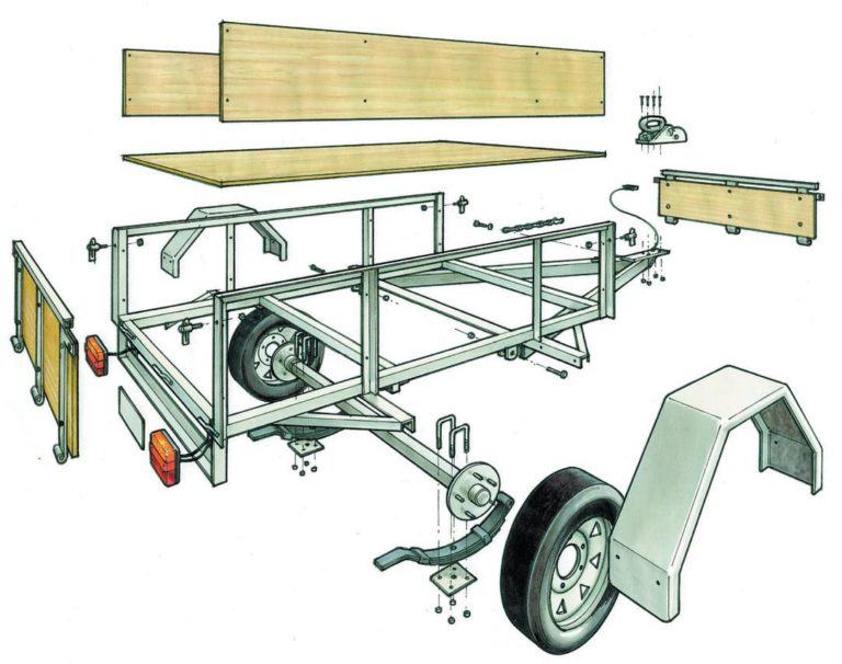
The trailer kit, including mudguards, wheels, lights, coupling and springs
The hydraulic kit
Sub-frame
Make the sub-frame at this stage, too. The sub-frame will be 150 mm shorter, because of the hinges. I make it now because I have already fabricated the top frame and it is true and square, so I can use it as a template for the second frame. I weld on the hinges at this stage, too.
Put the four rubber blocks between the two frames, and then sit the hinges in place. Set the two frames parallel to each other and weld the hinges to each half. Take out the hinge pins, put the sub-frame aside and carry on fabricating the main trailer body. Astute readers will see that I have made a mistake and got the hinges around the wrong way. It doesn’t matter, except it looks better the correct way around. Weld in the 40 mm x 40 mm x 5 mm angle cross-members at 600 mm centres.
The top mount for the hydraulic cylinder
Mounts
Now the critical part starts. We need to put in some mounts for the hydraulic ram. I have used a piece of 40 mm x 40 mm x 5 mm RHS welded between the two cross members, 890 mm from the rear. On this, weld the two top lugs which are supplied in the hydraulic kit, available from a hydraulic specialist. I tack these with the pin in to keep them aligned and square. It is important to note the position of these because the hole centres from the hinge to these is critical. Weld these on the front side of the cross member in the centre, 100 mm mm apart. For some extra support, I have welded two 25 mm x 25 mm x 3 mm RHS to the sides of these, then back to the front cross member.
IMPORTANT: These and the bottom mounts are probably the most critical part of this whole tipping project. They must be on-centre, they must be square and they must be parallel with each other and the trailer frame.
Testing hydraulic cylinder in its mounts. The cylinder should be extended by at least 20 mm and must not be bearing any load when the trailer body is down
Mount hinges to top rail (tail gate)
Use a block of wood to wedge the ram to the required position for the bottom mounts and fit the saddles and bolt them to the hangers
Hinges, toggles, lights
Weld-on the four corner uprights. I have made these a little heavier than on the original trailer be-cause, as a tipping trailer, some users may regard this as being more commercial and use it as such, so I have used 40 mm x 40 mm x 3 mm angle.
Another tip here is to drill the holes for the antiluce toggles before welding them on. Weld-on the top side rails. I have changed these to 25 mm x 25 mm x 3 mm RHS. This is as far as I go with the side. Don’t weld in the intermediate uprights or the guard brackets, although you may wish to have them cut out and ready to go. I will explain later why I prefer to do it this way. Next, weld on the tailgate and head-board hinge pins. This requires a bit of playing around. I found the easiest way was to fit the hinges, clamp them and, when happy, weld. With these on, I cut and welded the top bar in 25 mm x 25 mm x 3 mm RHS to the hinge straps. I made these with 5 mm clearance; i.e. 1205 mm.
Now bolt on the antiluce toggles to the uprights and set up the toggle plates onto the outer hinges. When butting two pieces of flat together for welding, always make sure you have a small gap to allow good penetration, especially if you are going to grind your welds flush.
For the lights and number plate protection boxes, I used 65 mm x 3 mm flat and, for the bases, 2.5 mm flat plate which a local sheet metal shop found in their scrap bin and cut to size for me for a small fee. There are several ways you could make these, for example, angle iron. I used what I had lying around.
The finished size was 130 mm x 130 mm left hand and 130 mm x 480 mm right hand. These are fully welded and cleaned up using a flap disc. They are then stitch-welded, flush with the rear uprights. For extra support, I plated in the top. The trailer body is basically finished now, so put it aside and bring back the sub-frame.
Test positioning of RHS ram-bracket supports
The A-frame, shown here after being galvanized
Drawbar
At this stage we have just a square frame with the hinges welded to it. The next stage is to make the draw-bar.
Cut two 65 mm x 35 mm x 3 mm RHS, 1800 mm long. Set them roughly on to the frame at 560 mm from the front cross member. Mark the centres of the front and rear cross members then, using a string line from the rear to front, intersect the two marks right through to the front of the A-frame.
Adjust the two RHS until dead centre, then tack weld them on. Re-check and when you’re happy, fully weld on the drawbar. These all have to be good welds because not only is this what keeps your trailer from spreading all over New Zealand, it is also going to be the main bottom mount for the hydraulic ram.
Drill the drawbar coupling plate and then mark the centre line of the plate. This plate is 80 x 250 x 12 mm. Clamp it onto the A-frame and centre it with the string line as you did with the A-frame. When centered fully, weld it off. Underneath this I welded on a piece of 50 mm x 10 mm flat bent at right angles, roughly 100 mm x 70 mm. Make sure you locate it clear of the bolt holes.
Setting up the springs and axle
The body guide plates to guide the body onto the sub frame as it lowers
Work with the trailer frame upside down
The springs, axle and hub bolted in place
Cylinder mount
Now fabricate the bottom hydraulic cylinder mount. For this, I used 40 mm x 40 mm x 3 mm RHS and 65 mm x 35 mm x 3 mm RHS. Cut the 65 mm x 35 mm to fit between the mainframes; it should be 1130 mm.
Now cut the 40 mm x 40 mm to fit between the drawbar A-frame. In my case, it works out to be 975 mm on the long side and 20 degrees angle.
Cut out the two 195 mm saddle mounts and drill 13 mm holes at 105 mm centres, 20 mm centre from top at 20 mm centre line. Because everything is becoming critical now, I tip the top body upside down and fit the sub-frame to it with the hinge pins fitted.
I then put the hydraulic cylinder into position with the top pin fitted and I extend the ram 20 mm.
NOTE: The cylinder must be always mounted with at least 20 mm extended and there must be no load on the cylinder when the body is fully down. The hydraulic cylinder is not part of the structural integrity of the trailer. The pins always have a lot of clearance to ensure the cylinder never becomes side-loaded as it raises the body.
Grind off a small amount of galvanising prior to welding on the rubber blocks
Ram check
Using a block of wood I wedge the ram to the required position for the bottom mounts and fit the saddles and bolt them to their hangers. Now fit the other two cross-members and bring everything together so the hangers are 180 mm apart measured to the outside, are on centre and flush with the back of the 65 mm x 35 mm RHS and sit-ting on it.
When you are confident every-thing is square and parallel, tack weld everything together. If you are confident with your tacks, you should be able to pick up the draw-bar and extend the ram through its full motion with no tightness or binding anywhere. If there is, it usually means something is out of square or out of parallel.
When you are happy that the work is square, remove the ram so that it does not get damaged and fully weld off all the components. For the two RHS, I just stitch welded them together.
Mounting the mudguards
Guide-plates
Leave the sub-frame and body together.
We now need two body guide-plates. I used two pieces of 50 mm x 10 mm flat plate. I heated and bent a rough angle at one end of each (about 20°) and then sculptured them so they will guide the body onto the sub-frame when coming down. I welded these to the inside of the body frames. They need to be a reasonably tight fit to avoid the body rattling too much. Unfortunately, after we had every-thing galvanized, it was too tight so we had to use some gentle persuasion—a 20-pound hammer—to gain some clearance.
Welding the rubber blocks in place; keep a bucket of water handy so the rubber won’t be affected by the heat
Axle
The next step is to make the axle.
I won’t go into too much detail here. It is absolutely critical to get it right and if the axle is something for which you require instruction, I would recommend you take it to a tradesman engineer to get it set up and welded. For those who are going to tackle this: the axle is 50 mm x 50 mm x 5 mm RHS, 1300 mm long. From the end to end of each stub is 1565 mm. Make sure you drill a couple of holes in the RHS roughly where the end of the stubs will be and plug weld the stub.
Weld the spring hanger-locating plates centred over the mainframe. With the axle, you need to decide where to locate it on the sub-frame. The centre line of the trailer is probably a good place to start. Personally I like to have a weight bias to the front, so I decided to try the axle set 50 mm to the rear of centre measured from the front. This is 950 mm.
I then tacked on the spring hangers and slippers and assembled the whole axle group including hubs and wheels. I don’t fit the hub seal or grease the bearings and I hold the wheels on with only two nuts. This is only a temporary fit up to ascertain the location of the weight bias.
Use a bearing grease-packer
Greased bearings
Bearing packed
Weight
Enroll some help and roll the whole assembly over onto the wheels.
Bolt-on the coupling and fit the hydraulic ram, tailgate and headboard. With all this fitted you will have a good indication of the weight on the front.
I picked up the front on the coupling and used a spring scale to measure the weight at 40 kg. This is about right, except that I still hadn’t fitted the hand-pump and oil and had not fitted the decking, so I figured the axle would need to come forward 20 mm, or 930 mm from the front. It was only a small job to roll over the trailer, cut the tacks and shift the spring and axle assembly for-ward 20 mm. I now recorded 20kg. I was happy with this so my next task was fitting the mudguard brackets; the guards need to be centred over the wheels.
Zinc-passivated ram brackets
Uprights
I also fitted side uprights beside the guard brackets. Do not bring these or the guard brackets below the bottom bearer. I made all these out of 30 mm x 30 mm x 5 mm angle. The diagonal braces off the guard brackets also serve as extra load restraint points.
It was time to stand back and see what I had forgotten. The bottom subframe needed a cross member to stiffen up the assembly so I put a 44 mm x 40 mm x 5 mm angle, 600 mm from the back. This is directly underneath the body one.
Hydraulic ram attached to sub-frame
Clean-up
Next, strip down the whole assembly and go around all the joints to make sure they have been fully welded.
Then run over the whole fabrication with a flap disc and remove any TIG wire and spatter and generally clean up any rough welds or sharp edges. Drill the necessary breather holes at the ends of any parts that have been sealed off 8 mm in preparation for the galvanizers. Don’t worry if you miss any, because the galvanizers will do it, but they will charge you extra.
Before going to the galvanizers, you also need to drill all the holes for the hand-pump safety chain and the sideboards and headboards. Don’t worry about the deck because I am going to use self-tapping deck screws.
When all the parts come back from the galvanizers, you need to re-drill all the holes to clear out the galvanizing. I then assembled the bearings and seals into the hubs. I use a bearing grease-packer to ensure the grease gets right through the rollers. When fitting the hubs onto the spindles, do up the nuts to finger-tight only.
Lifting top frame into place
Rubber blocks
With the sub-frame sitting on its wheels and before fitting the body, I fit the four rubber blocks. These are vulcanised onto steel backings.
They can be screwed, bolted or riveted on, but I prefer to weld them on. Grind a small strip of galvanizing off the sub-frame where you are going to weld. Paint the underside of the block with cold galv. Clamp and weld a block into each corner. I have a large bucket of water handy and quickly cool each weld so the heat doesn’t affect the rubber. Clean the weld areas then paint with cold galv. and finish as-sembling the rest of the trailer. This should be fairly straight forward as you have already roughly assembled and dismantled it a couple of times.
Lights fitted to side, clear of tipping deck
Sides and deck
For the sides and deck, I used one-and-a-half sheets of 17 mm H3 CD ply. The deck is 1800 mm x 1200 mm; each end is 300 mm x 1200 mm and the sides are 300 mm x 1765 mm—these fit inside the end-boards.
I stained these with deck stain and allowed them to dry be-fore fitting them. I used 6 x 30 mm coach bolts, two in each upright. For the deck, I pre-drilled the holes 5 mm for the deck screws and fit-ted them to each cross-member at centres.
Hydraulic ram mounted between sub-frame and tipping deck
Wiring
Next, fit the lights and run the 5-core wiring.
I am not into having all the wiring hidden inside the frame—save that for the hot-rodders. I run it inside one of the drawbar’s RHS arms and then cable-tie it to the rest of the channels. I take the main cable up to the right-hand light at the number plate and then run the cable for the left-hand light from this termination, across the rear cross-member up to the left-hand light and neatly strap it to the frame using cable ties. Leave approximately 400 mm protruding from the front and fit the plug.
Mounting hydraulic pack on drawbar
Hydraulics
Bolt the hand-pump onto the drawbar.
Notice the 50 mm x 10 mm stiffener plate. I have drilled two new holes in the hand-pump mounts, centre of the existing holes. This saved having to fabricate another mount on the draw-bar. Fit the male/male adaptors, one to the hand-pump outlet and one to the ram port.
Make sure you fit the dowty washers first. Fit the high-pressure hose right-angle at the ram. The hose is going to rotate with the ram, so you need to have the deck down and position the hose so that it will be clear of the road. Fill the tank with hydraulic oil, close off the valve and start pumping.
Check the movement of the hose and when you happy that it won’t interfere with anything else, secure to the frame with a couple of heavy cable ties.
DANGER: NEVER LOOSEN ANY HYDRAULIC FITTINGS WHILE THE BODY IS RAISED. IT WILL COME CRASHING DOWN.
To lower, turn the valve anti-clockwise.
Filling hydraulic tank mounted on sub-frame
Wheels
Finally, adjust each wheel bearing. Jack up each side and tighten the castle nut to just-firm but not too tight. Spin the wheel a few times and check it is not dragging and not too loose, i.e. there is no play in the bearings. Back off the nut slightly until one of the slots aligns with the hole in the spindle and fit the split pin. Pack some grease into the dust cover and gently tap this on. Fit the safety chain, stand back and admire your work.
Fitting the pre-stained decking.
Pumped up …
…and tested