Make a stylish timber stepladder
By Bob Browning
The top shelf in my walk-in wardrobe is 2.3 metres above the floor and I need a small stepladder to access it. I used a small, aluminium stepladder for some time but decided to make one that was compatible with the furniture, from timber. The design was done by modifying the design of the aluminium stepladder for timber construction. My starting point was the tread depth which was 75 mm on the aluminium ladder. I wanted to make this deeper to make it easier to climb. I also wanted to increase the width of the sides which is, of course, related to the tread depth.
Greek architects determined several millennia ago that the most attractive proportions of a room were 8:5 or 1.6:1. I try to maintain this ratio when designing anything rectangular that I want to look well-proportioned and the top board complies with this.I used macrocarpa for this ladder as I usually do for projects of this type, largely because it is reasonably available locally but also for its qualities as a timber.
Small stepladders are now available which incorporate a safety handrail. Clearly, this is a good feature for those with unsteady balance. I chose not to incorporate this in my stepladder because it will be kept for use in my walk-in wardrobe, a small room where it is possible to rest a hand against the wall for balance.
Setting blade angles on saw
Timber
I bought 100 x 25 mm rough-sawn timber for the treads and sides and dressed it on my thickness planer. The edges of the timber were damaged and the best width I could obtain was 92 mm. In the ladder, this would become the tread depth which required the width of the sides to be 80mm, which seemed reasonable.
The finished thickness of the timber for the treads, rails and top board was 22mm which I can usually get from 25 mm rough-sawn timber. I prefer this to the 18 mm dressed timber commercially available.
The longitudinal and transverse angles for the sides, with the stepladder open, I took straight from the aluminium ladder. I made the width of each tread similar to those of the aluminium ladder but increased the height of the whole stepladder a little to 870 mm. Allowing a thickness of 13 mm for each backboard, and 1 mm for the hinge, I came up with a top board (tread) consisting of two pieces each 370 mm x 115 mm. This gave a combined top board dimension of 370 mm wide x 231 mm deep, with the stepladder opened up for use. This top is somewhat larger than the top of the aluminium ladder but I decided that was an improvement.
Bob checks with sliding bevel
Treads
With the ladder open and viewed from the side, the angle of each side is at 18° from the vertical; when viewed from the front (or rear), the sides taper outwards from top to bottom, each side at an angle of 4° from the vertical. The trenches in the sides are therefore a compound angle, and this makes them relatively difficult to make but not excessively so. I first made the treads, two pairs of different lengths. After selecting the top face on each piece, I planed the back edge to 18° from the vertical. The ends were cut 4° to the vertical to be parallel to the sides.
I ripped down the sides and edge-planed them to a finished width of 80 mm, then cut them to length and trenched them to take the treads (through housing joints). The cuts for the ends and trenches are compound cuts of 18° and 4° and were done on the sliding compound mitre saw.
The angle settings on my mitre saw are accurate enough for carpentry work but not sufficiently accurate for detailed work such as these treads. To improve accuracy, I cut a piece of MDF 150 mm x 350 mm and cut angles of 18° on one end and 4° on the other. I then used this to set the blade angles on the saw.
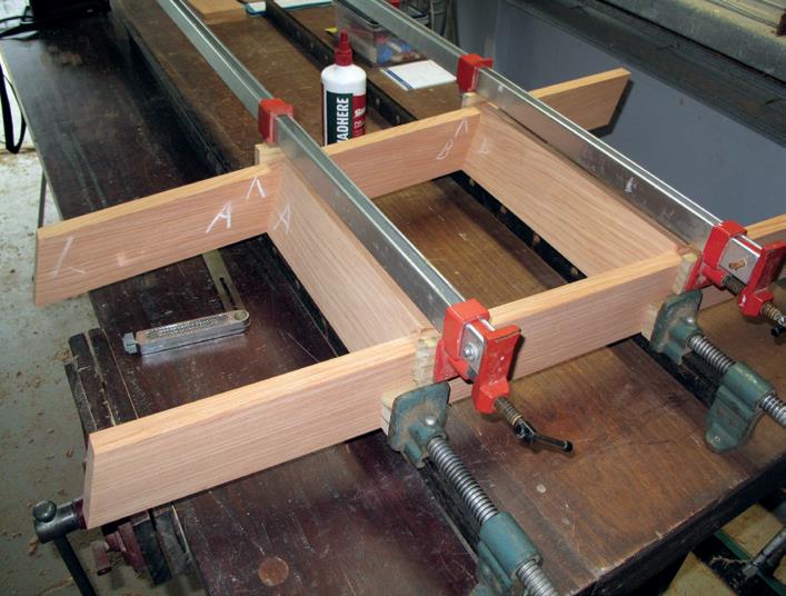
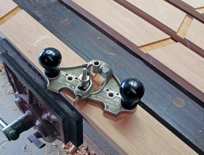
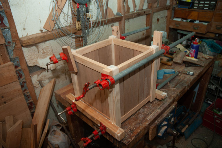
1: Hand router plane cleans up trench cuts in sides 2: Glued and cramped assembly. Tapered packers protect timber from jaws
Sides
I first cut all sides to length then raised the blade to make the trench cuts. Raising the blade on my saw has the effect that it will not cut right through at the set depth, so I find it necessary to place a packing piece against the fence to effectively move the fence outwards. I always pass this packer through the thickness planer to ensure the sides are parallel.
By making a series of overlapping cuts, I removed all material from the trench. But because the blade is tilted, the teeth are lower on one side than the other and the bottom of the trench is left relatively rough. The best tool to clean this up is a hand router plane, and I used mine to do so.
Before starting to glue up, I planned the gluing process and used blackboard chalk to mark where pieces go. Then I drilled the sides for fasteners to go through into the treads and glued the treads into the sides.
Stepladder dimensions
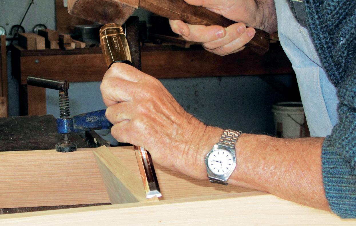
1: Chiselling off tread end
To protect the timber while the cramps held it, I cut tapered packers to place between the sides and the jaws of the sash cramps. I set a sliding bevel to the required angle to check that angles were correct after assembly. I use PVA glue and am careful to wash off any glue that has squeezed out, using water. This ensures it does not leave a long-term mark which would show after the timber had been finished.
The top of each tread when the ladder is assembled extends past the sides by 7 mm. This is because, while the sides slope back at 18°, the front of each tread is vertical. I chiselled off this part of the tread which jutted out, just at the corners, cutting them back at 45° in a single plane so that the interface between the side and the tread forms a single straight line.
Back boards
I next made the back boards, which have the top edge planed at 18° and gave them an overhang of 5 mm past each side. These provide lateral stability for the ladder, so I glued and screwed them to the sides, keeping the top surfaces flush with the top of the ladder sides.
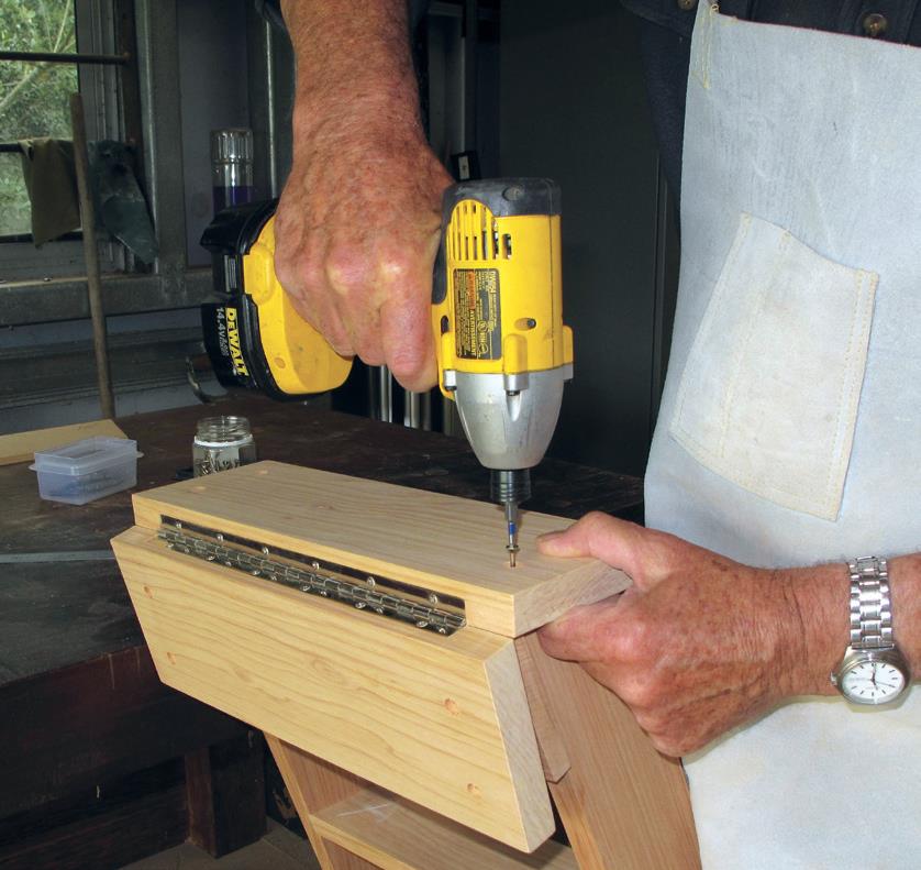
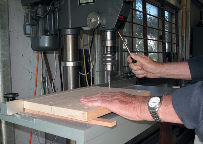
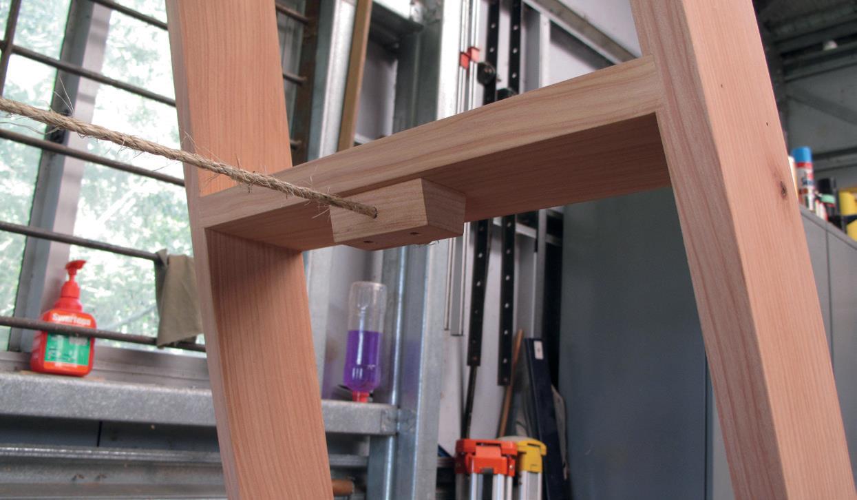
1: Drilling holes in top boards 2: Rope is knotted behind screwed cleats
Top board
The two pieces for the top board were next. Traditionally, hinges are screwed to the back board, but in this case I elected to use a continuous hinge 300 mm long, and rebate it into the back edge of each top board piece. I used stopped rebates to match the length of the hinge. When it was closed, the hinge was 5 mm across so I routed rebates 2 mm deep in each piece of top board to leave a central gap of 1 mm when the stepladder was open for use.
The width of the rebates equated to the measurement of the hinge from its edge to the centre of the pin with the hinge closed; 14 mm for the hinge I used. I marked locations for screws in the top board, then drilled a hole 3 mm deep at each location to take a wooden plug to
cover the screw head. I drilled the screw holes and then screwed the top board to the two sets of sides, keeping the protruding part of the hinge hard against the back boards. To make plugs to cover the screw heads, I used a Veritas tapered plug cutter which produces tapered plugs which fit tightly into the receiving hole. A length of 6 mm sisal rope is the traditional stay between the front and back frames. Under the lower treads, I glued and screwed cleats which were drilled with a 6 mm hole to take the rope that is knotted behind each cleat.
Ladder closed shows hinged top boards

