The Shed Logo
Search
Close this search box.

Warning: boiling point!

I own an American classic car and it comes with the usual 1960s instrumentation—speedo, fuel gauge but only warning lights for oil, alternator, and water temperature. The alternator light comes on when you turn on the ignition, but the water temperature light is designed to come on only when the water temperature reaches 120-125 °C which is usually too late. To fix that, I have devised this program powered by an Arduino micro-controller that will operate the temperature light when the engine powers up and light it up again to warn the driver as the temperature approaches 100 °C. It uses a readily available sender that will fit most vehicles.

Install an Arduino-run water temperature light in a classic car
By Mark Beckett
Photographs: Mark Beckett

Warning light
Mark tightens sender on the engine block

I own an American classic car and it comes with the usual 1960s instrumentation—speedo, fuel gauge but only warning lights for oil, alternator, and water temperature. The alternator light comes on when you turn on the ignition, but the water temperature light is designed to come on only when the water temperature reaches 120-125 °C which is usually too late.
To fix that, I have devised this program powered by an Arduino micro-controller that will operate the temperature light when the engine powers up and light it up again to warn the driver as the temperature approaches 100 °C. It uses a readily available sender that will fit most vehicles.

How it works
The software is configured to operate the light for five seconds when the ignition is turned on, just like modern car warning lights. As the vehicle warms up, the light is continuously brightened until the engine reaches normal temperature, when the light goes out.
Water that is not pressurised will boil at 100° C so if the temperature gets to 90 °C (“hot”) the light will start flashing rapidly, and if it climbs to 100 deg C or more, it will stay ON.
While the design will work with the sender and the software settings I used, there is a facility to calibrate the “normal” setting to cater for a different thermostat temperature. If you use a different sender (which may have a different resistance), I felt it was safer to modify the sketch (software). There are notes in the sketch to help with this.

Freetronic shield, completed top side
Freetronic shield, completed underside

Controller
I chose to use a shield (add-on board) to house all the parts for this project that allows the use of any standard Arduino and settled on a Seeeduino V3.0 and a Freetronics prototype shield as an inexpensive solution.
I used the controller and shield to for the previous variable wiper speed project for the car (“Wipe that classic windscreen,” Shed, Apr/May 2012). This second part uses the same controller and shield to do both tasks. The reader can either make one or both. The shield construction includes the extra parts (two resistors, one transistor, and one diode) and uses the “Start” button to do the “Normal” calibration.
There are two sketches (software)

Sender and temp sensor...
...together for accuracy
Mark records values as sender is heated and cooled

Sender
David at Auto Agencies ( www.autoagencies.co.nz ) helped me to pick a commonly stocked and easily sourced Facet sender (7.3005), which costs under $20 GST-inclusive and fits American cars. This temperature sender has a negative temperature co-efficient (NTC) which means the resistance decreases as it gets hotter allowing more current to flow. If the car had a gauge, more current flowing through would move the needle to show the water temperature was hotter.
In this project, 5v is fed through a 150 Ohm resistor to the sender and the voltage across the sender is measured using an analogue pin (A0) on the Arduino controller. As the engine temperature rises, the sender resistance lowers and the voltage at P1 pin4 (A0) reduces so the light
The Arduino analogue pins map input voltages between 0 and 5 volts into integer values between 0 and 1023. This gives a resolution of: 5 volts / 1024 units or 0.0049 volts (4.9 mV) per unit (204 per volt).
see http://arduino.cc/en/Reference/AnalogRead
From my measurements, 65 deg = 2.92v, 90 deg = 2.07v and 100 deg = 1.84v, so the Arduino sees 65 = 598, 90 = 424, 100 = 377.
We can also use the value to determine if the sender is disconnected (1023) or shorted (0).

Light control
The controller checks the input every 0.5 seconds and uses the value to determine if the water temperature light should be
fading (below 65 °C),
off ( 65-90 °C) ,
flashing (90-100 °C) or
on (100 °C or greater) as well as indicating a fault with the sender.

For the Off and On, the output is either LOW or HIGH.
digitalWrite(TempLight, LOW); or
digitalWrite(TempLight, HIGH);
To flash, we toggle it between LOW and HIGH at a set rate.
For the fading we use a technique called “pulse width modulation” (PWM) where the output is switched between Off and On at a very fast rate. The On time versus Off time determines how bright the light is.
For the example below the ‘fadeValue’ range is 0 (off) to 255 (on).
analogWrite(TempLight, fadeValue);
There is a very good explanation at http://en.wikipedia.org/wiki/Pulse-width_modulation
Lamps (and LEDs) are not linear devices, meaning if you apply the voltage half the time (fadeValue = 128), the lamp will not be at half brightness. You can change the range that ‘fadeValue’ uses to compensate and give the appearance of an even fade.
As I mentioned in part one of this series [https://the-shed.nz/wipe-wipe-that-classic-windscreen/],
we use the timer (
millis() ) to check the time, rather than adding any delays that would slow down other processes.

Resistance shown on meter, temperature on the LCD display
Taping the sender before fitting into the adaptor

Construction
In the Mar/Apr issue, we detailed the shield construction. The schematic shows the water temperature light connections in black with the variable wiper connections in red.
The Start and Calibrate buttons can be a piece of wire that gets connected to ground when you need to calibrate the unit. If you have built the variable wiper unit shown in the Mar/Apr issue, the Start button is already fitted.
This application also has some alternative construction ideas. If you intend to control the existing water temperature lamp (12v) you will need a transistor to isolate the Arduino from the 12v. The alternative is to connect the anode of a white LED (with resistor) to D6 and connect the cathode to ground.

Be nice to your controller
In this project, as an example of being nice to your micro-controller, we use a transistor to drive/control the water temperature light.
There are two reasons:

  1. Increased current. The Arduino can only supply 40mA max, while the lamp may require 100mA
  2. Higher voltage. The Arduino (and any integrated circuits or ICs) should never have a voltage applied to their inputs that is higher than the operating voltage (5v).

In our example we need both reasons.

Tightening the sender into the adaptor
Sender hole, more accessible with hoses removed
Sender fitted

Program
In Arduino speak a program is called a sketch and you will need the Arduino IDE in order to upload the sketch.
This is available at http://arduino.cc/en/Main/Software and I recommend using version 023 (at time of writing, Arduino 1.0 has a few issues).

  • Download the sketch from the Downloads bar at the top of The Shed magazine website and save it (unzip as required).
  • Connect your controller to the computer.
  • Run the Arduino IDE, load the sketch into the software by selecting File – Open, then pointing to where you saved it.
  • Select the correct Serial Port and Board under Tools.
  • Click on the upload icon (2nd from the right) and it should compile and upload.
  • When it finishes, disconnect, and fit the shield onto the controller.
The completed sender ready for fitting. The adaptor has been reduced to allow the sender more exposure to water

Installation
The first part of this series [https://the-shed.nz/wipe-wipe-that-classic-windscreen/]
details the case used and the wiring. If you intend to use only the water temperature light function, you do not require the Start and Stop buttons or the Wiper Relay to be fitted.
You will need to identify the temperature sender/temperature light wire and cut it at a suitable point in order to connect the sensor side to P1 pin4, and the light side to P2 pin2.
The alternative is to use a white LED (and resistor), remove the water temperature lamp and arrange for the LED to fit where the lamp holder was. A rubber grommet will hold it there. Some of you, for one reason or another, may not completely trust a little black thing with legs. The schematic shows an optional temperature switch across the P2 pin2 output, just as the vehicle would have arrived from the factory.
This simply grounds the temperature light when it reaches the temperature-switch value and turns the light on (like the interior light example in Part One [https://the-shed.nz/wipe-wipe-that-classic-windscreen/] ).

Hoses restored. Spot the sender

Calibration watch
For calibration, you will need to measure the resistance of the sender at 65 °C (thermostat), 90 °C and 100 °C. A small amount of calculating is then required to use these new values. (It may also require you to use the kitchen and a pot, but wait until the wife is out.) A watched pot never boils but with patience you can get your 
LCD visible (part of a spa pool controller) to show the temperature and measure the resistance with a meter. As the sender slowly heated I recorded the values, ensuring the two parts were together for accuracy.
I also noted the temperature resistance on meter and temperature on the display at rolling boil (see I do know the terms) and also noted the temperature on the cool down. The sender has mass, so it did lag a bit.

Calibration
The sketch has been set to work with a 65 °C thermostat and the Facet 7.3005 temperature sensor. If your thermostat is different you may need to adjust the “Normal” value by either modifying the sketch before loading it or adjusting it once it’s installed in the vehicle.
To adjust the “normal” value in the vehicle:

  1. If the Start button is not fitted, either fit a wire or pushbutton to P2 pin 6.
  2. Short the Cal input (P2 pin4) to ground BEFORE turning the ignition switch to Acc or On.
  3. The input can remain shorted and the light will flash twice, then stop for two seconds and repeat.
  4. Start the vehicle and the temperature light will flash twice, then stop for two seconds and repeat.
  5. Monitor the temperature and when the thermostat opens and the vehicle is at normal temperature, press the Start button.
  6. The temperature light will change to flashing five times, then stop for 1-2 seconds and repeat, signifying the new “Normal” value has been stored.
  7. Remove the Cal input (P2 pin4), and switch the vehicle off.

If you wish to use a different temperature sender, then you will need to modify the sketch to accept the new values. You will need to measure the resistance of the sender at 65 °C (thermostat), 90 °C and 100 °C. A small amount of calculating is then required to use these new values. (It may also require you to use the kitchen and a pot, but wait until the wife is out.)

Normal running
Warning

Testing
Obviously after you connect it, its essential to check that it works. Every time you turn the ignition on, the temperature light should illuminate for five seconds then either brighten to “on” as the vehicle warms up or turn off if the vehicle is warm. This is the normal Power On Self Test (POST) that proves the light and sender are working.
If the sender is disconnected

  • the light will flash three times then stay off for two seconds and repeat the cycle. After repairing this, switch the ignition off and back on to reset it.

If the sender is shorted to ground

  • the light will flash four times, then stay off for two seconds and repeat the cycle. After repairing this, switch the ignition off and back on to reset it.

The need to reset faults by switching the ignition off and back on is deliberate. Any faults that are intermittent will be noticed and some action taken to rectify the problem.
CAUTION: During these faults, you cannot detect the engine temperature so take care. In cold weather, during the transition from warming up to normal, there may be some jumping from one state to the other, while the thermostat settles down and the radiator water warms up. If this happens you may consider adjusting the “normal” temperature up or down slightly.

Share:

More Posts

The Shed September/October 2021 Issue 98 is on sale now

Glen Macmillan works between his two sheds creating sculptures from recycled waste. His junk of choice is gardening tools, landscaping equipment, and farming equipment — particularly the older kind of hand tools that were made to last and had a bit of styling.

Simple hydroponics nutrient solution

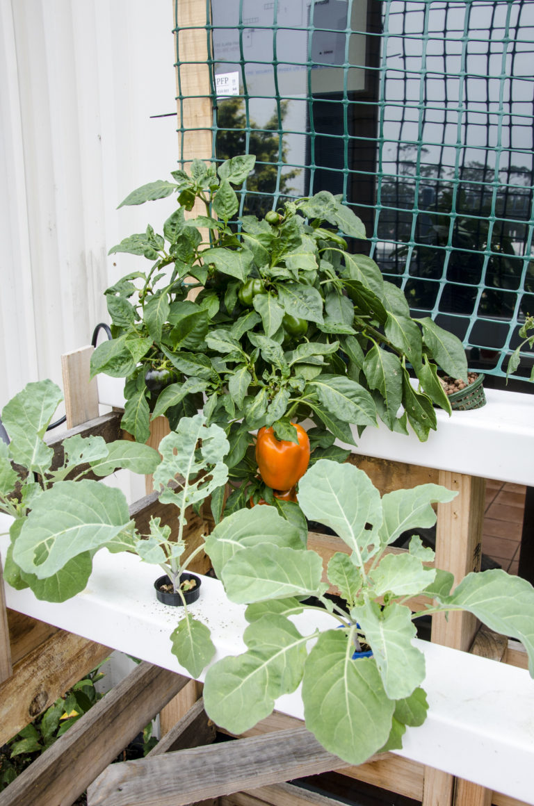
Hydroponics is all about growing without soil. In many ways, this simplifies the lot of the gardener, but it gives them added responsibility for providing plants with the right level of nutrients.
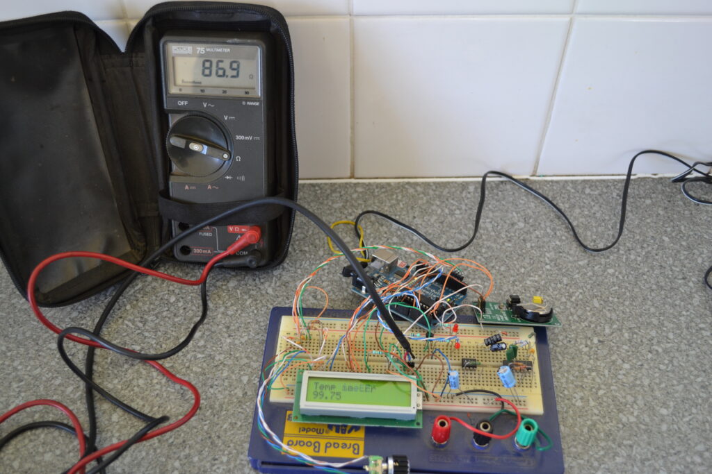
As water with nutrients tastes, feels, and looks much the same as plain water, a testing instrument called an “EC meter” or “CF meter” is used.

Making a word clock

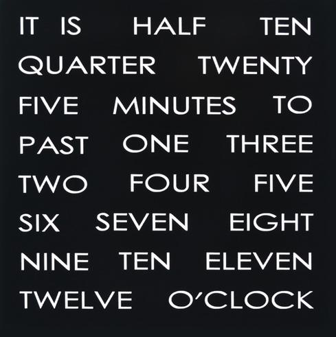
The Word Clock is a project created by Doug Jackson using Open Source (www.dougswordclock.com) and has been evolving into the product you see here.
It is based on an Atmel 168 processor chip as used in Arduino, is programmed using Arduino and fitted into a custom-made printed circuit board (PCB).