
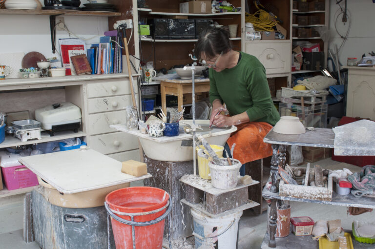
Christchurch potter Renate Galetzka draws inspiration for her colourful and quirky pots from her daughter’s stint as a circus trapeze artist and the books of Dr Seuss.
“I want to make people smile,” says Renate, whose pots are fanciful but functional, made to be used not left on the shelf. “I make pots to brighten your day every day.”
German-born Renate met her Kiwi husband, Liam, in the Abel Tasman National Park in the 1980s. “I was on an OE and I’m still on an OE,” she declares, and part of that on-going overseas experience included discovering the art of ceramics. She took hobby classes in Christchurch, followed by “work experience” with one of the grand dames of New Zealand pottery, Frederika Ernsten, looking after her gallery in return for lessons. Renate went on to run and teach pottery at the Risingholme Community Centre.
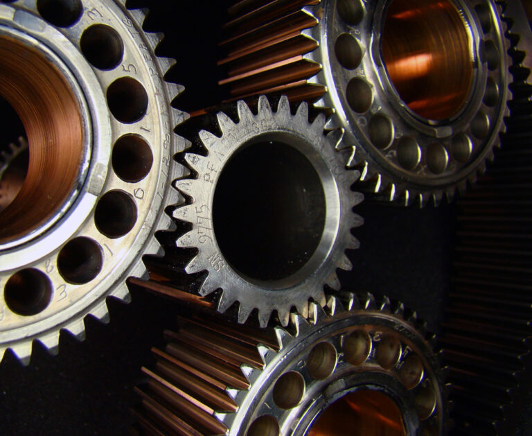
As sheddies, we are known to cobble together machines from whatever we have at hand. More often than not these items are less than ideal and a motor of some sort may run at a different speed to what we need. If we are looking to make a spindle moulder, belt sander, garden chipper, wind generator, compressor or similar item then it is likely that some sort of gearing will be necessary to give the right RPM at the business end.
Calculating the sizes of gears, sprockets or pulleys is a relatively simple exercise. Below is an easy reference to save having to work it out from basic principles each time.
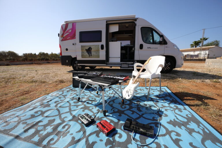
Introduction to electronic music – part one – instructional video
Have you ever imagined yourself as a John Bonham or a Jimi Hendrix? The magic of electronic music means you can set up your own one-man band, create original masterpieces, or rearrange your favourite instrumental.
In this new series in The Shed magazine, Enrico Miglino shows just how easy this can be with advice on what tools and aids are needed to get you started.
This video is to accompany part one of the series published in the October/November 2024, issue 117.