Soldering on Part One

Everyone knows that at some stage you need to blame your tools (after the other excuses have run out), and like most things you can pay a little money or a lot, and sometimes there is little difference in the result … or so it would seem. The purpose of this article is not to separate you from your hard-earned cash, but to share a few tricks and provide some information to make an informed choice when buying equipment. Everyone knows that the best soldering iron is some large lump of material that you throw into the fire until it is red hot and then apply to the job and hope that some of the exploding material fuses the bits together. That might work for joining two bits of metal together but it is not going to work for electronics. Soldering electronics is not only mechanical bonding, but also making an electrically conductive joint. The solder used has a particular temperature range and too hot will ‘cook’ the joint and make it porous, while too cold means it sticks to one or other part but doesn’t bond.

All soldering equipment is not created equal. Here are some tips and tricks
By Mark Beckett
Photographs: Mark Beckett

Solder Pumps. Phillips is on the left. Note the smaller lengt

The other day I was having a conversation with The Shed editor, Greg Vincent, and I realised that although we have been doing a variety of articles on electronics, we haven’t talked about the tools needed to do decent work.
Everyone knows that at some stage, you need to blame your tools (after the other excuses have run out), and like most things, you can pay a little money or a lot, and sometimes there is little difference in the result … or so it would seem.
The purpose of this article is not to separate you from your hard-earned cash but to share a few tricks and provide some information to make an informed choice when buying equipment.

Stations and irons
Everyone knows that the best soldering iron is some large lump of material that you throw into the fire until it is red hot and then apply to the job and hope that some of the exploding material fuses the bits together.
That might work for joining two bits of metal together, but it is not going to work for electronics.
Soldering electronics is not only mechanical bonding, but also making an electrically conductive joint. The solder used has a particular temperature range, and too hot will ‘cook’ the joint and make it porous, while too cold means it sticks to one or other part but doesn’t bond. 
The basic soldering iron consists of a heater and a tip. The wattage is limited to 25-40W to stop overheating the tip. It works well on small joints and relies on the thermal mass for larger joints.
Because it takes time to warm up, it tends to get left on, and there have been attempts to reduce the heating with inbuilt or aftermarket controllers, much like a light dimmer, which simply reduces the power applied and, therefore, the maximum heat.
Clever versions detected the iron was in the stand and put full power back on when lifted, but the thermal lag becomes a nuisance and often is bypassed.

Correct iron and solder placement (photo is without heat to show placement)
Desolder pump placement while heating the solder joint

Temperature-controlled irons
Weller produced a version that controlled the temperature by using a magnet inside the tip. As the tip heated to the desired temperature, the magnetic force reduced and switched off the heater. As the tip cooled, it switched back on. The tips were expensive but lasted for many years if looked after.
Since then, electronics has taken over and there are a range of stations with adjustable temperature control, either by using a setting or a knob. 
Some models include active measuring of the tip temperature, although I have never really paid any attention when I’m soldering – it’s either hot enough or not.
The temperature control approach has allowed a much higher wattage iron to handle the wide range of solder joints we find on modern circuit boards.
As a consequence, the time to warm up has been reduced, along with the thermal mass problem with larger joints.
Rework stations often include a soldering iron, but if I were to purchase one separately, I’d be looking very hard at this: http://nz.element14.com/tenma/at980d-eu/soldering-station-80w-220vac-eu/dp/253519201 especially as it’s currently on special (shown by the 01 on the end of the part number).

Proper solder joint
When introducing the subject of electronics, pupils are taught how to solder and how to recognise the difference between a good solder joint and one that may cause problems later.
Mount Fuji is an example of a good solder joint. When viewed in profile, it has a curve or fillet in the transition from horizontal to vertical on both sides (well, it does in the pictures).
The board (PCB pad) and component wire are heated equally, and then solder is applied to complete the joint. This whole process takes less than five seconds.
Applying heat to a PCB pad for much longer is likely to lift the pad from the board (giving you another issue to deal with), so unless it is a very large joint, keep the heating time to a minimum.

Solder joint where the solder has not adhered to the component lead either due to oxidation or wrong technique

The state of flux
One issue we see is that the iron is placed on the joint, and solder is applied onto the upper surface of the tip, rather than at the junction of the pad and component. Solder for electronics contains a resin flux and gets burnt off when incorrectly applied.
The smoke and visible fumes are indicators of this happening, along with dark flux residue on the board.
By applying solder down at the intersection of the board and component, you’ll be able to see it melt and disperse. At this point remove the solder, THEN the iron.
Adafruit has a very good guide to soldering and problems: https://learn.adafruit.com/adafruit-guide-excellent-soldering
Soldering takes practice, and some people never seem to be able to master it, so don’t worry if you struggle … you’re not alone.

Poor solder joint
So now we have a good soldering iron and we use the correct technique, so what can go wrong?
For proper bonding to occur, both surfaces need to be clean and shiny. If the components you are using have been sitting around, then the tin coating may have oxidised, which can cause problems.
You can ‘tin’ the component lead before inserting it, or sometimes the soldering process (flux) will clean it.
Tinning is where you apply heat and solder to the component only, and the result is a light coating of solder. It may release impurities (often dark-looking residue), so sometimes a quick wipe is required to be sure it doesn’t get into the solder joint.
If the board is not shiny, then a pencil eraser works wonders to remove any oxidation.

Using gravity to assist removal of excess solder
Solder has not adhered to the component lead either due to oxidation or wrong technique
Too much solder which could be masking a poor connection to the pcb pad

Solder solutions
You may have applied too much solder and the joint is covered, so you can’t be sure if it has bonded.
My first solution is to use gravity to remove excess solder. I turn the board upside down and apply heat to the solder joint, then pull it down the component lead and away from the joint.
The next solution is to de-solder it. The guides always talk about finished solder joints being nice and shiny, and while that is true for lead-based solder, the move by manufacturers to lead-free solder results in a dull surface.
SMD (Surface Mount Devices) solder joints are far less obvious, and the technique, tools, and solder to join the component to the board is different.

De-soldering
This is the process of removing solder, usually with the aim of separating the component from the PCB.
There are several methods, and each has its place and cost for the tools required.
For this article, we will talk about cheap, simple tools, and in a later article, we will touch on desoldering stations.

De-solder braid/wick
I’ve heard people swear by de-solder braid/wicks, and I’ve heard people just swear.
Solder wick is a copper braid-like product that soaks up the solder. It is more suited to SMD but is useful to remove excess solder.
It comes in different sizes and there are some cheap products which cause more frustration and damage than they are worth.
The technique is to apply the soldering iron onto the wick and then onto the solder joint. The heat goes through, and it pulls the solder away from the board.
The heat and force can lift solder traces, so be careful about how long it is used in one spot.
It is very useful for cleaning up holes, but then so is a solder pump.
Don’t be fooled – they come in different widths and the cheap stuff may not work as well.
This soldering guide is rather good, and they use the braid/wick to clean up the joint:
https://www.sparkfun.com/tutorials/96

The through-hole soldering guide is here:
https://learn.sparkfun.com/tutorials/how-to-solder—through-hole-soldering

Solderwick. 2.6mm width in a handy dispenser
In part two we will look at Desoldering Stations like this

De-solder pump
These are a tube with a spring inside that is released, causing a vacuum at the tip. The soldering iron and de-solder pump are applied to the joint, and once the solder is melted, the spring is released, and the solder gets sucked up the tube.
It is a bit of an art but with some luck mixed dexterity, you can easily suck all the solder from the joint. Again, excess heating of the pad can cause it to lift.
De-solder pumps work well on one or two joints but can be a pain to use.
To use them, you press down the plunger to compress the spring. Heat up the joint and bring the nozzle as close as you can, then press the release button.
As the plunger is released it sucks up the hot solder inside the pump. Obviously the closer the nozzle is to the joint, the more effective it is.
The best model I have is a Phillips-branded version that is slightly smaller than others and utilises a smaller nozzle. This means you’re not fighting the soldering iron for the same space, and the suction velocity is higher.
I should have brought three or four at the time because they don’t seem to be available anymore, so I’m looking after mine.

Buy and try
Something to watch for are models where the nozzle is inserted from the outside.
When you push the plunger down fully, it protrudes through the nozzle to clean out any solder lodged on the sides. With the external-insertion type nozzle, they can be pushed out.
Models with softish nozzles can deform rather than clean out properly.
The only maintenance is to make sure the O-ring is clean and lubricated, and check the nozzle is not damaged. Along with replacement tips, they should outlast your ability to keep soldering.
It’s rather hard to see all these things just from looking at a catalogue, so don’t be afraid to ask at your local suppliers or buy different types until you find the one you want.
If you have smaller hands, the length can also be very important as they are meant to be used with one hand. Element14 have a good range in varying types and prices, and you can expect to pay from $5-$70. 
My suggestion is to buy one that screws together, as I’ve seen the others fly apart.
I usually stretch the spring to apply suction more quickly however some argue that Mr Newton’s equal and opposite force means it makes contact with the heated pad and increases the damage.
Whatever version of solder pump you buy, make sure you grab a couple of extra tips.

Share:

More Posts

3D Printing

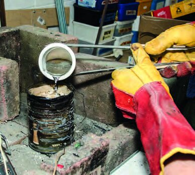
Here we’re going to use 3D printing to do a modern twist on “lost wax” casting.
It’s a trick that’s more than 5000 years old: make something in wax, bury it in clay or plaster leaving a hole in the shell. Bake the heck out of it to remove the wax and then pour molten metal down the hole. If everything stays together, you get a metal replica of your wax object.

Make your own Kontiki for fishing

There are several New Zealand-designed and created fishing kontikis on the market but when I thought about having one, I wasn’t going to buy it.
I had the ability, so I did what any good Kiwi would do, I decided I would make one myself.