Create a reflector telescope on a simple Dobsonian mount
By Gordon Hudson
Photographs: Andrew Labett, Gordon Hudson
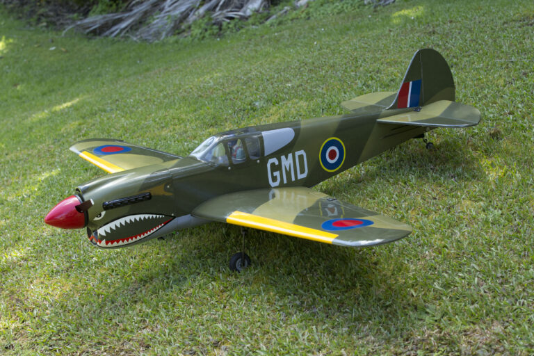
Gordon Hudson and Dobsonian reflector telescope.
Turning tube
This a project to make a popular Newtonian-design reflector telescope with a Dobsonian mount. The principle of the telescope is to collect light and then magnify the image. The light from a distant object (a star or planet) is gathered by the mirror and brought to a focal point. The eyepiece is used to focus and enlarge the image. By changing the eyepiece, we can increase the magnification and the size of the image. The larger the objective or mirror the more light it can gather and therefore you can use a higher magnification eyepiece.
The advantage of the reflecting telescope where the objective, the mirror, can be made bigger to gather more light and can be made to a shorter focal length (see the section, Focal ratio, focal length), is that the whole system can be compact.
Scalloping side bearers
Mirror mount without mirror
Mirror mount profile
Marking mirror
Newtonian
The Newtonian telescope consists of two mirrors, a curved primary mirror and a small flat mirror called the secondary. The primary mirror is ground to a very accurate concave shape. The secondary has to be perfectly flat and elliptical and the correct size calculated to match the primary mirror. It is easier to make a line drawing of the optical lines and then measure the correct size of the secondary.
The secondary mirror has two measurements. As it is an oval shape, we refer to these as the minor and major axis. We are only concerned with the minor axis. This mirror is placed at 45° and when viewed at that angle it looks to be round.
There are four basic types of mounts, altazimuth, equatorial, fork, and Dobsonian. Here I make the very simple and very stable Dobsonian-style mount which was created by American John Dobson who wanted to popularise astronomy with a telescope on a simple mount that could virtually be taken out onto the footpath for use.
A Dobsonian mount can be built with woodworking tools. It turns on a wide, stable base of two round, flat wooden discs pivoting on a central bolt with pieces of Teflon or PTFE plastic to help the discs rotate round 360°.
Focal ratio, focal length
The focal ratio is the focal length of the lens divided by the diameter of the lens. For example, the focal length of a lens (1200 mm) divided by the diameter of the lens (100 mm) equals 12, therefore the focal ratio is F12.
The primary mirror is ground to a very accurate concave shape so that the focal point is x distance from the mirror. e.g. 150 mm diameter mirror with a focal length of 1200 mm. The focal length (1200 mm) can be divided by the diameter of the mirror (150 mm) eight times, so we refer to the mirror as an F8 focus. A shorter focal length say, 900 mm, and a mirror diameter of 150 mm will give you 6, making the mirror an F6.
Remember the smaller the number on the eyepiece the higher the magnification. This is because the number of times you can divide the eyepiece focal length into the focal length of the mirror or lens is greater with a shorter focal length eyepiece.
Mirror within skirt
Fixing on side bearer
Mounting mirror base
Mirrors
First, you need to decide what diameter mirror you want to have and you need to decide what focal ratio you want of the standard ratios normally available e.g. f4, f5, f6, f7, f8. I don’t recommend you grind your own mirror which is very time-consuming and needs expertise but you can buy one of the good imported mirrors from Astronomy New Zealand (owned and operated by the Auckland Astronomical Society, www.astronz.co.nz.
The popular 8” F6 mirror is an excellent size to start with. (Astronomy refers to the main mirror diameter in inches but also uses metric.) The telescope that I am building here has a locally made mirror and is a 10” (250 mm) F6.7 (1676 mm)—perhaps a bit too long for the Dobsonian type mount which would better suit an F5 or F6.
The secondary mirror diameter for this telescope is 50 mm on the short axis—remember the secondary is an elliptical shape 50 x 70 mm. The focuser you need is easier to buy than make. A Finderscope is an essential accessory, usually a 50 mm aperture with a magnification x7 or x8. A half of a binocular can make an excellent finder although it will not have any crosshairs in it which can be helpful. You will also need a couple of eyepieces—I would recommend a 9 or 10 mm focal length and a 25 mm focal length eyepiece.
Tube
Although it can be expensive, I prefer a round plastic pipe tube to the wooden square tube some people like because wood can be lighter and creatively shaped.
The diameter of the tube should be clear of the mirror all round by 25 mm. The regularly available culvert tubing I am using is 305 mm inside and 315 mm outside diameter. I managed to scrounge it from a friendly farmer. Tubes of this ID come in two different wall thicknesses 5 mm and 8 mm. It pays to go for the thinner tube as this is lighter.
The tube needs to be about 300 mm longer than the focal length of your mirror. Remember there are no set rules for building a telescope, just a few guidelines. My tube for this project is 1900 mm long. I made the base of the telescope out of 16 mm MDF and the mirror mount of 20 mm MDF. All screws are stainless steel but the bolts are just nickel-plated. It is most important to paint the inside of the tube black. I used blackboard paint.
Mirror mount
I made sure the ends of the tube were square by spinning the tube in a homemade lathe. I am fortunate I have a lathe where I can spin a length of three metres by 350 mm diameter or a disc of up to a metre in diameter. I made a couple of tight-fitting discs to fit in each end of the tube and used a chisel to square up the end of the tube.
Out of 20 mm-thick MDF, I made the two wooden discs for mounting the mirror, one exactly the same size as the mirror and the other a snug fit into the tube. I fitted four 75 mm x 8 mm bolts into the wooden disc on which the mirror sits so each round head was just below the surface. The bolts, three-quarters of the distance from the centre and 90° apart, are used to adjust the mirror. A fifth bolt 40 mm long is fitted into the centre of the larger disc and protrudes up by about 15 mm; the mirror disc will sit on this bolt which acts as a pivot point.
The pivot bolt head sits on a flat washer sunk into the under-surface of the mirror mount; this prevents it sinking into the wood. Four flat discs of rubber about 30 mm in diameter are glued to the surface of the mirror disc and the mirror will sit on these rubber pads which are evenly spaced around the disc.
Four springs about 30 mm long are fitted over the bolts between the two discs. Put a washer on either side of each spring. The bolts pass through the second disc. The four holes for these bolts should be larger than the bolt at 9 mm. This will enable the mirror disc to be moved up and down freely so that the mirror can be collimated.
A washer and wing nut are fitted over each bolt. The wingnuts are tightened on the springs until the mirror disc is sitting on the centre bolt where it pivots, allowing us to adjust the mirror.
The mirror is held in place on the wooden disc with a skirt, here a piece of Formica heated to the exact diameter of the mirror and disc. The skirt is equal in height to the thickness of the mirror (30 mm) plus mirror disc (20 mm) combined, plus 5 mm so the skirt will sit above the mirror face. Here, four stops are glued to the inside of the skirt to stop the mirror from falling forward.
It is most important that the mirror is not held firmly as this can distort it. The skirt and the holding lugs should have a fraction of a millimetre clearance. You should be able to turn the mirror when the skirt and lugs are properly fitted, although sitting on rubber pads it may not turn easily.
Centre ring
A centre ring is fitted to the mirror while it is still on the bench. Mark a cardboard disc the same diameter as the mirror, using a compass so the compass point will give you your centre.
Cut the disc out and enlarge the centre hole to about 2 mm. Lay the cardboard disc over the mirror face and centre-dot the mirror through the hole using a felt tip pen. Remove the cardboard disc and place a self-adhesive paper ring about 8 mm in diameter over the felt tip mark you have made. Then you can carefully wipe off the felt tip mark leaving behind the paper ring. This gives you the centre of your mirror and will be important when it comes to collimating your mirrors.
Before fitting the side bearings, you have to find the balance point of the telescope. You can only do this with the telescope fully assembled, so the mirror mount with the mirror in place has to be installed in the bottom of the telescope tube.
The mount should far enough up the tube to allow the collimating bolts and wing nuts to be about 20 mm clear inside of the bottom of the tube. The distance up the tube should place the screws into the centre of the bottom plate. Wood screws about 40 mm long hold the mount in place. Pre-drill holes so the wood doesn’t split. The bottom plate of the mount should be about 40 mm up the tube and an even distance from the bottom edge all the way around.
Placing the spider and focuser is the tricky part. To place the spider we need to know the focal length of the mirror, the diameter of the telescope tube and height of the focuser. This will be easier shown in the diagram as these measurements are critical.
Critical measurements are also;
* the position of the secondary mirror;
* the distance from the secondary mirror centre to the holding screws in the spider vanes.
This is added to the measurement of the distance from the main mirror to the secondary.
The secondary directs the image at right angles to the light path and so the diameter of your tube and height of the focuser are most critical.
Remember to fit an eyepiece into the focuser as this may also upset the balance of the tube. With the optics and focuser placed, the Finderscope is fitted close to the focuser. The photo of the finished telescope gives you an idea of where to place this.
Once you have found the balance point of your telescope, make sure the focuser position is rotated by turning the tube until the focuser is at about the 10.30-time position. Then mark the position of balance with a cross on both sides of the tube 180° apart. This is where you are going to place the two side bearings on which the telescope will pivot on.
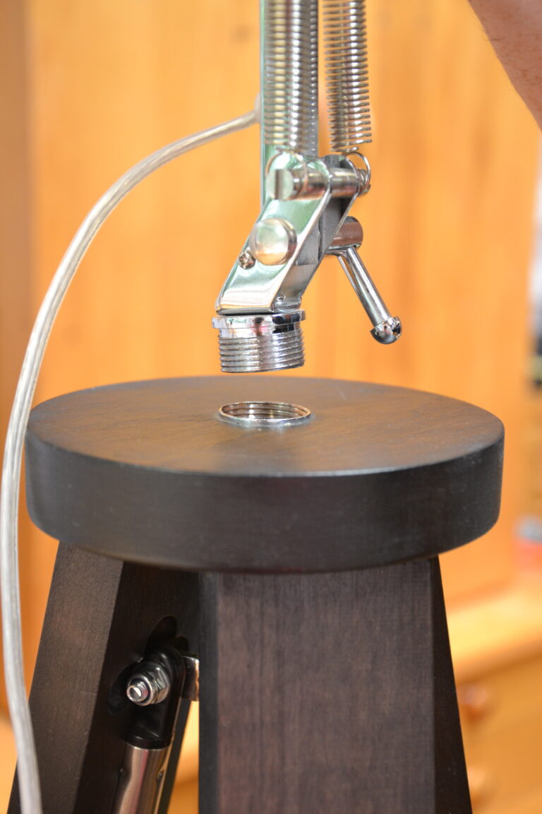
Fitting focuser
Positioning spider
Fitting finder
Side rocker bearings
To make the rocker bearings, I cut 150 mm-diameter plastic tube with 10 mm wall thickness to 75 mm. A smaller telescope can use a smaller diameter tube. To fill the centre of this cut plastic tube, I made a block of two pieces of 20 mm MDF glued together and cut round to fit tightly into the side bearing tube where it is glued.
The trick with the rocker bearings is to scallop out the shape of the bearings to fit nicely against the telescope tube. To get the desired curve, I hold the side bearing against 80 grit sandpaper glued to the surface of a rotating drum with the same diameter as the telescope tube.
Bolt (and glue if you wish) the side bearings in place through 10 mm holes drilled on each side of the tube. You may have to remove the mirror mount to be able to put your arm up the telescope tube to tighten the nuts of the side-bearing bolts.
I use bolts long enough to take an extra lock nut so a tensioner spring can fit to the side bearing and tension the rocker—you don’t want the telescope to move up and down too easily.
Secondary with dot
Dobsonian mount
Work out the height of the mount sides as the distance from the bottom of the telescope tube to the bottom of the side-bearing plus 75 mm to allow for the telescope to clear the bottom of the mount when it is pointing vertically. Allow about another 75 mm for the cut-out where the side bearing sits in the mount.
The whole Dobsonian base is about 16 mm thick and its size depends on your telescope. My base is 600 mm in diameter; for an 8-inch (200 mm) telescope I would use a 500 mm diameter base.
The base needs two discs and the sides of the mount are screwed and glued to one of these circular bases. The spacing for these is the diameter of the tube plus 10 mm extra each side. The curves the telescope sits in are governed by the diameter of the side bearing plus 5 mm. Two pieces of Teflon are tacked into place on each side of the curved cut-out for the telescope to ride on. Small adjustments to the Teflon may need to get the telescope moving smoothly.
A backplate, low enough so the telescope can point horizontally, holds the sides firmly in place. A curve in the top edge of my backplate matches the curve o the telescope tube. A gusset and low front plate—to let the telescope tube pass over—strengthen the sides.
Three rubber feet on the bottom of the lower base let the telescope to sit on rough ground. On top of the lower base, tack pieces of Teflon spaced at intervals around the circumference and about 70 mm distance from the outer edge. To the upper base plate, I glued a Formica disc the size of the base disc to allow the Teflon to run on a smooth surface. A 12 mm coach bolt through a centre hole allows the top plate to rotate over the bottom plate. A washer and wing nut tension the two plates.
A pair of heavy duty tension springs on the outsides give extra tension to the rocker. They are attached from the centre bolt in the side bearing to a bolt fitted partway down the side of each side panel of the mount.
All that is left to do now is to paint your mount but otherwise it is finished.
See Collimate the telescope; the final step to align the optics later in this article
Finished telescope. Note tensioner spring on side
Secondary mirror
The easiest way to calculate the size and position of the secondary mirror is to show you a drawing of how we determine the size and position of the secondary. You will need to draw your own line drawing and this will depend on the size and the focal length of your mirror.
The formula for calculating the diameter of the secondary mirror is:
a = (D – d) c + d
f
where:
a = Minor axis width of secondary mirror.
D = Diameter of primary mirror.
d = Diameter of focal plane to be illuminated (typically 12 mm for visual use on 1.25-inch format systems).
c = Distance from focal plane to secondary mirror (typically with focuser in mid-focus position).
f = Primary mirror focal length.
Newtonian diagonal and size placement
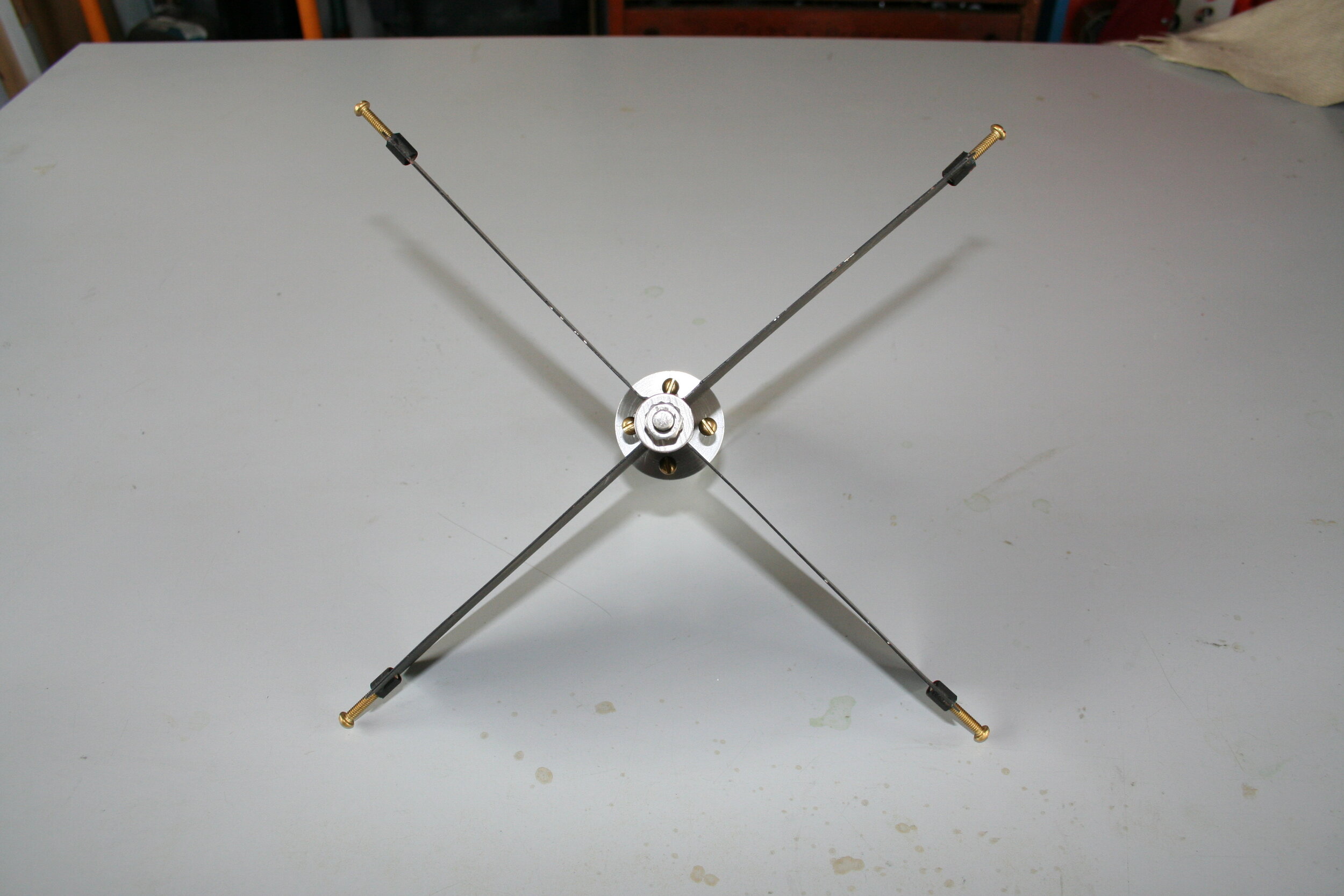
Secondary holder (spider)
The secondary holder or spider is the only metal part of the telescope. Four vanes about 1 mm thick and made of steel, brass or aluminium support the secondary mirror. I use brass because it is easy to solder while steel and aluminium would need to be welded (not easy).
There are many ways this spider can be manufactured and you can even buy one. The central post of the spider is hollow for the bolt which gives the mirror up-and-down adjustment. I have used a piece of square brass tube with a hole around 7 mm in diameter and approximately 80 mm long. The vanes 70 mm deep are tapered to 50 mm.
The vanes, sitting flush with the bottom of this central tube, are soldered or brazed to each flat surface of the tube. Small brass bolts, the adjusters, are brazed or soldered to each end of the vanes to hold the spider in place.
The length of the vanes is determined by the diameter of the spider’s central tube and the inside diameter of the telescope tube. I find it easier to draw this on cardboard full size using a compass. I find the centre of the telescope tube, draw the 12 mm square inside the tube, then measure off the length of the vanes. Allow each vane to be about 5 mm short of the outer tube to give you a little sideways movement.
Next, I make the spacer and the diagonal that actually holds the secondary mirror. The 20 mm-thick spacer is smaller in diameter at 40 mm than the secondary mirror which is 50 mm on the short axis. Four holes are drilled and tapped into the spacer. The holes are evenly spaced at 90° apart and three-quarters of the way out from the centre
The bolt that passes through the centre of vanes will go through the centre of the spacer and be locked against the central tube of the spider with a nut. The bolt I used is actually a length of 6 mm threaded rod. Brass 4 mm machine screws about 50 mm long act as the adjusters for the secondary mirror. These are screwed down through the tapped holes in the spacer which will fit nicely between the vanes.
The aluminium block that holds the secondary itself is smaller than the mirror and is 40 mm in diameter, the same as the spacer. It needs to be about 50 mm long with one end shaved off at 45° and the other end square. This can be done with a hacksaw and then squared and flattened with a sanding block. Check using an ordinary 45° set square.
A 7 mm hole mm drilled through the centre of this diagonal holder allows the 6 mm threaded rod to pass through. The larger diameter for the hole is so that the secondary holder will be a loose fit. A fixing nut on the end of the threaded rod stops the mirror holder from falling off. To enable the nut to be fixed in place, a larger hole has to be drilled from the 45° end of the holder about three-quarters of the distance up the existing hole. Do not drill right through. I burr the end of the thread so that the nut will not come undone. It is a good idea to measure the centre of the secondary and place a black dot with a felt tip pen at its centre.
The secondary held by four brass screws can be collimated by adjusting the screws to get the correct angle.
To fit the secondary mirror to the diagonal, I used Gorilla Grip glue. Before assembling the spider, I painted the vanes with flat blackboard paint. You can now assemble the spider using nuts to lock the threaded rod to the centre shaft where the vanes are attached. The threaded rod needs to be only long enough to allow about 20 mm up-and-down movement of the secondary.
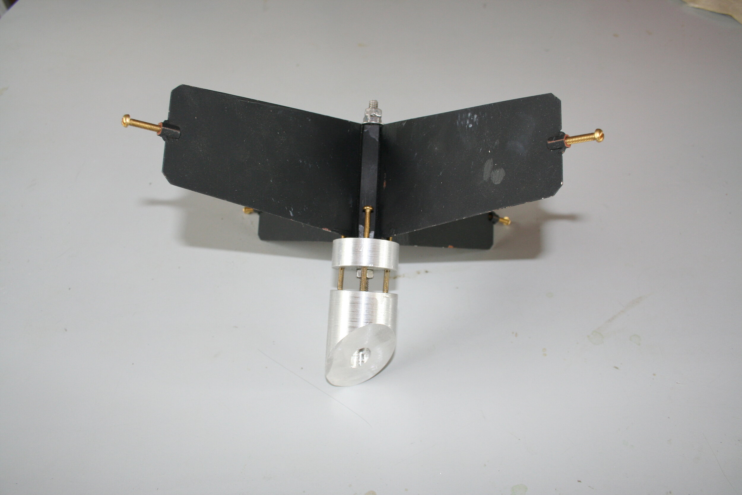
Spider assembly
Bottom view
Top view
Now that you have finished building your telescope we need to align the optics; this is called collimating.
There are various ways of collimating the telescope. I will explain the easiest method, using a Red Laser Pointer. This method also uses two plastic film canisters. Kodak film canisters fit into the focuser perfectly; other makes may not fit.
In the first canister, drill a 2 mm hole in the centre of the cap and in the centre of the bottom. In the second canister, make a hole in the bottom about the same size as the aperture of the Laser Pointer which we are going to mount in it. Make a couple of mounting rings from a cork tile to hold the laser in position in the canister.
Telescope maker and restorer Gordon Hudson in his “shed.”
Parallel
It is essential that the beam from the laser pointer is parallel to the sides of the canister.
There is a simple way to check this, using the canister sitting in a V slot in a block of wood. I cut a V in a piece of 200 mm x 50 mm.
Lay the canister in the V, making sure the lip of the canister is forward of the edge of the V, and secure the block so it doesn’t move. Aim the laser dot on a wall or some other surface about one metre away and mark the spot with an “x”. Then rotate the canister with the laser in it.
The dot should stay still as you rotate the canister. If it doesn’t, it means the laser is not centred in the canister. You will need to make some small adjustments to the laser in the canister until the dot remains in the spot while you rotate.
Use the focuser
Check laser down open end of the telescope
Collimate
Having got the two canisters finished we are ready to collimate.
First, place the canister with the lid on and holes in top and bottom in the focuser and wind the focuser fully extended. If you look into the hole in the top of the canister you will see through to the secondary mirror and you should see the black dot that you put on the secondary mirror when you were making the spider.
If the dot is not in the centre but up or down, then you need to move the secondary mirror up or down to place the dot in the centre. This is done with the centre bolt on the spider that you made. If the image is not centred from left to right, you will need to rotate the secondary mirror until it is clearly in the centre.
Now remove the first canister and replace it with the canister with the laser in it. Turn the laser on and look down the open end of the telescope tube. The laser dot should fall in the centre of the main mirror where you previously placed a small self-adhesive circle. If it is not in the centre, adjust the secondary using the three small adjusting screws behind the secondary mirror until the image falls in the centre ring.
The secondary mirror is now aligned with the main mirror. However, we now have to make sure that the main mirror is squarely facing up the tube and not pointing to one side.
This is done in the evening where we use a bright star.
Use the dot…
…on the secondary mirror
Circle on the main mirror for collimating
Bright star
Point the telescope at a bright star and get it into the centre of the eyepiece. Use the 25 mm eyepiece for this. Wind the focuser so that the star is out of focus and you will see in the eyepiece a round disc of light with a black round disc in the centre. The black disc is the secondary mirror blocking off the starlight in the centre of your mirror.
That black disc must be precisely in the centre of the disc of light.
If it is not, then you adjust the main mirror by adjusting the three bolts at the bottom behind the mirror until the black image is in the centre. You will only need to make very small adjustments on these bolts—about a quarter of a turn should be ample or maybe even less. It is easier to do this with two people.
Refocus the telescope and look at the star. It should be symmetrical. If the star has a flare out to one side, the telescope’s main mirror is still not correctly collimated and therefore you need to make further adjustments to the main mirror’s collimating bolts. Test on star image again and it should be symmetrical.
While you are looking at the bright star, align your finderscope on the star by adjusting the alignments screws around the outside of the finder. Your telescope is now finished and collimated and ready to use.
You can purchase a cheap laser pointer from the $2 shop that will do the job. You can also purchase a proper laser collimator from www.AstroNZ for $75 and you can then do away with the film canisters.
There are other ways of collimating without the laser just be using the eye but this requires a bit more skill and practice.
The Dobsonian mount telescope
Adjusting centre bolt at base of spider