A guide to electronically controlling a 3-phase motor in the home workshop with a VFD
By Geoff Merryweather
Photographs: Geoff Merryweather
The ever rapid and constant development of electronics has had many positive effects for the sheddie, and one such example is the Variable Frequency Drive (VFD), which allows the speed of 3-phase motors to be electronically controlled with the bonus of adjustable speeds. Historically, continuously variable speed motor drives involved mechanical systems such as the Reeves drive, which is similar to a motor scooter CVT transmission where belt-drive pulleys can be varied in size “on the fly” and hence vary the drive ratio.
These and other transmissions were universally expensive, difficult to retrofit and inefficient. The increased use and falling prices have brought new and used VFD drives within the reach of the home user and have opened opportunities with industrial machinery that previously did not exist.
My introduction to VFD drives was with my 1951 Colchester Chipmaster lathe. These lathes came from the factory with a Kopp Variator mechanical drive and no gears other than the 10:1 spindle back gears. The Kopp allowed a speed range of 300-3000 rpm, and when it finally died, I fitted a second-hand PDL Xtravert drive.
“It is not perfect and hence can lead to harmonic noise and ‘cogging’, or rough movement at low speed”
Electric motors
The standard electric motor sets the speed based on the line frequency (50Hz) and the number of sets of windings (called poles) in the motor. A 2-pole motor runs at around 2800rpm, 4 pole at 1440rpm, 6 pole at 960rpm and 8 pole at 720rpm. The difference in frequency is the reason why motors in America run 60/50th of the New Zealand speed due to their 60Hz line frequency – e.g. a 4- pole motor in New Zealand is around 1440rpm, where it is 1730rpm in America.
A universal motor such as the brush-type motors used in a hand drill set the speed on the voltage, hence a voltage controller such as a light dimmer or autotransformer can be used to adjust the speed. This cannot be used for a synchronous induction motor, as it will eventually burn out or draw excessive currents while remaining running at the name plate speed.
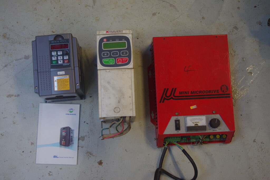
The VFD provides a variable frequency supply to the motor at a constant voltage, hence the speed of the motor can be varied. This speed variation can be above and below the rated speed – with limitations. Older VFD drives simply set the frequency and therefore the motor speed, such as the PDL Microdrive in Figure 1. If the motor load was too much then the speed would drop without the VFD correcting for the slippage. Newer VFD drives help to reduce this by indirectly measuring the torque requirements of the motor and boosting the motor power on the fly to maintain the speed setting. These are called sensorless vector drives and, while they usually cost more, they give a wider useful speed range.
An important point with VFD drives is that they can only work on 3-phase motors. If you have a single-phase motor (e.g. the motor is plugged directly into a 230V standard wall socket) then it will need to be changed for a 3-phase motor. These are common, reliable and cheap second hand so it is often not a major issue to change to a 3-phase motor from a single-phase motor. The problems usually come from any ancillary contactors, relays and controls, and getting it to fit in the space.
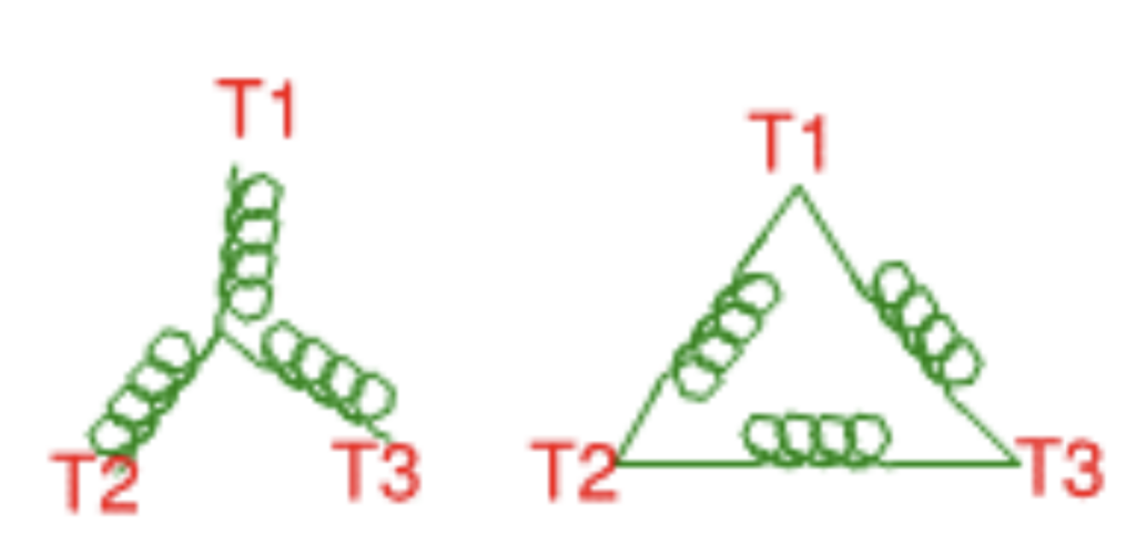
The way the motor windings are connected is also important, and there are two types of winding connection. In a delta connection, the opposite ends of three coils (one for each phase) are connected together in series. In star connection, the ends of three coils are connected together to form the neutral point (see Figure 2). The standard 440V motor is star wound by default and needs to be delta connected for operation on 230V. This becomes important as most VFD drives output the same voltage as the supply, so to run a motor on 230V single phase at full power, the motor needs to be wired for 230V.
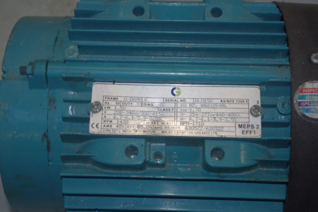
Many newer 3-phase motors can be changed from star to delta by changing connections in the terminal box. Check the name plate (see Figure 3) and see if it can run on dual voltage, and look in the terminal box on the motor if there are instructions. If it is not able to be changed easily, then options are:
- A motor rewinder can change the connections within the motor.
- Replace the motor with another one that can be changed.
- Use a transformer to increase the supply voltage to 400V and a 400V in/400V out VFD.
- Use a VFD that can take 230V in and output 400V. They are not common but are available.
What is a VFD?
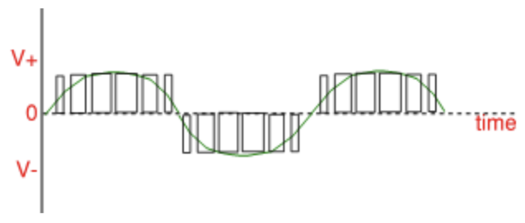
A VFD converts the line voltage and frequency (50Hz, single or 3-phase input depending on the model) to a 3-phase output with the frequency altered to suit the speed required. It does this by providing a varying width voltage pulse which is smoothed to approximate a sine wave. It is not perfect and hence can lead to harmonic noise and “cogging”, or rough movement at low speeds. As the frequency and voltage is controlled by the microprocessor in the VFD, it allows controls over the motor operation to be programmed into the VFD. This includes the rate of acceleration and deceleration on start-up, change to pre-set speeds on a control signal, motor braking and emergency stopping, and remote control switching. Many manufacturing or air conditioning processes connect multiple VFD drives together under computer control to synchronise operations.
“There is no such thing as a free lunch and there is a trade-off for speed against performance that some mechanical variable speed drives don’t have”
Advantages and limitations
VFDs bring a number of advantages to home machine tools. Even with gears or stepped belt pulleys, being able to alter the speed over a wide range without changing gears is convenient, and being able to slow the machine down below the lowest speed makes operations such as threading and power tapping easier. VFDs can also increase the motor supply over 50Hz, so that the motor can run faster than the listed speed. The amount of over-speed you can achieve depends on the motor, the quality of its windings and how well balanced it is. Aside from the practical limit of bearings and balance, the motor windings limit the top speed when they reach their limit for the magnetic flux developed in the windings, so the motor simply cannot go faster. A rule of thumb is a maximum of around 75Hz or a 50 percent increase in speed for a 4-pole motor.
There are advantages beyond the obvious one of a variable speed. The big advantage for the home user is the ability to run 3-phase motors on a 230V single-phase domestic supply. As above, this requires the motor to be wired to 230V 3 phase and the VFD being able to take a 230V single-phase supply, or be the type that can take 230V in and output 400V.
Other advantages include the ability to ramp up to speed instead of being abruptly switched. This reduces driveline stress and the start-up currents by spreading the acceleration over several seconds, so that a heavy load such as a lathe chuck can be spun up to speed within the limits of the available allowable current of the power supply and VFD. VFDs can also allow braking and controlled deceleration.
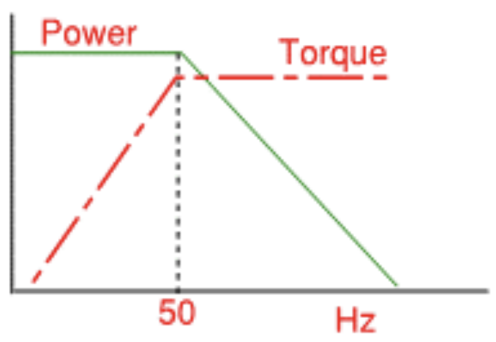
There is no such thing as a free lunch, and there is a trade-off for speed against performance that some mechanical variable speed drives don’t have. VFDs have traditionally been used for air conditioning fans and pumps and they are ideally suited for this as the torque requirements reduce as the speed drops. Machine tools have constant or increasing torque requirements as the speed drops, and this is where one of the limitations of VFD becomes apparent. As the speed drops below 50Hz, power remains constant, but the torque available reduces (see Figure 4).
When I originally installed the VFD in my Colchester Chipmaster, I used a 4-pole (1440rpm) motor, controlled by the VFD. I found that the loss of torque was a problem as the speed was reduced with large pieces and heavy cuts, especially since this machine does not have any other way of adjusting speeds. This limited the speed range, especially at the low end as it could not usefully go much below half or one-third speed.
The solution was to use a second-hand 4hp, 6-pole motor. As the motor is more than twice as powerful at a given speed up to 50hz, it has twice the torque at that speed and hence a wider useable speed range and low-end speed. The VFD also overdrives the motor to 75hz, giving the top speed of 1440rpm, so the useful speed range of the motor is from around 250rpm to 1400rpm with the turn of a knob. For fine work or threading where there is little torque required, it will go slower. Note that due to the extra windings, 6 and 8-pole motors have larger frames, which can make installation more difficult on an existing machine. They are also much less common than 2 and 4-pole second-hand motors, and more expensive to buy as new motors.
An issue to be aware if you are running heavily loaded motors at low speed is cooling, as the cooling fan on the end of the rotor is running at much less than its expected speed. If it is an issue, a computer fan on the end of the bell housing will provide additional cooling.
Installation
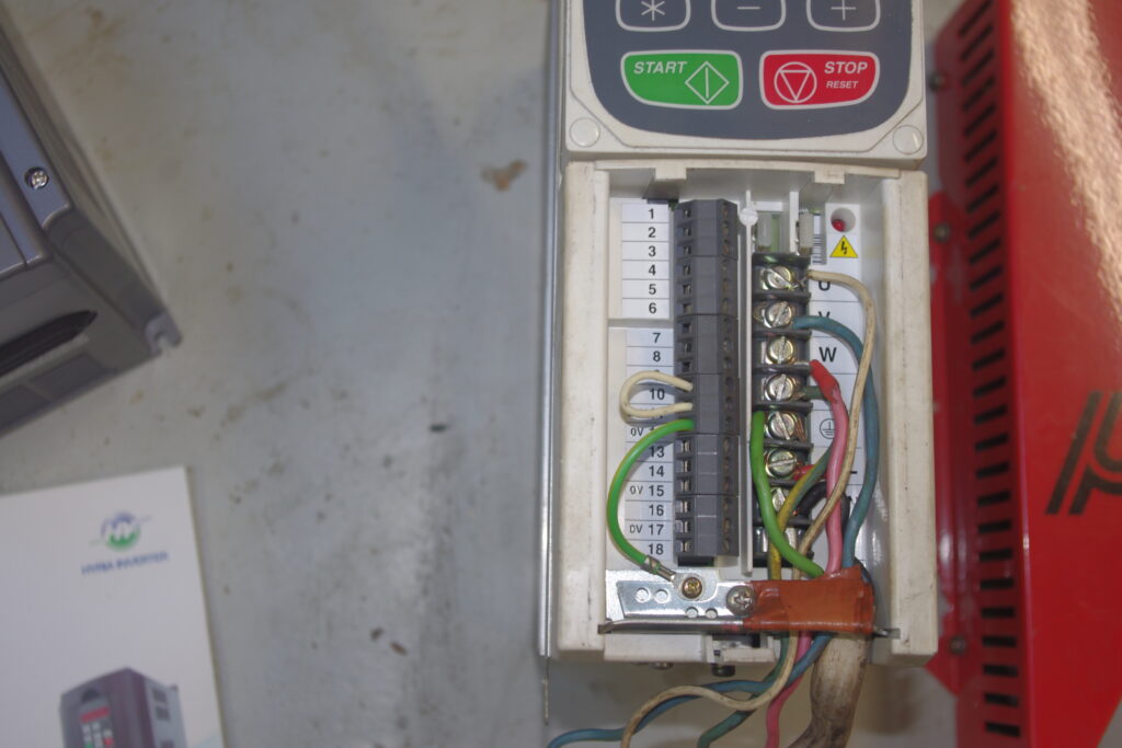
As VFDs have developed, they have become increasingly more complex and adjustable. The early drives such as the PDL Microdrive (Figure 1) had only a speed control knob and a power switch. More recent VFDs are highly programmable and require some set up. Getting a VFD without an instruction manual in English or being able to download one online can be an exercise in frustration if you need any more than the default settings.
While the wiring is not hard for someone who is careful and can follow instructions, it will legally need a registered electrician to do the connections and certification.
VFD manufacturers usually specify shielded cable to reduce noise affecting radios and other equipment. Having said that, mine have been running on unshielded cable for many years.

Selection
The set-up will vary according to the VFD model, however the general requirements are the same.
The VFD needs to be selected to match the supply voltage and motor voltage requirements, and the power or current draw of the motor. Get a VFD larger than the minimum you need for the motor to give you the flexibility to use it on other machines. It will provide more allowance for the start-up currents when you start under load or with high inertia loads, such as heavy lathe chucks. Remember also when you run a 400V motor on 230V, the current will approximately double as well, so you need to work within the limit of your single-phase supply.
The VFD instructions will say how to programme the drive for the maximum current allowed to provide overload protection, and the acceleration time on start-up. If you are on the limit of your available current capacity of the VFD, look at a longer acceleration time to reduce the peak current load.
“Getting a VFD without an instruction manual in English or being able to download one online can be an exercise in frustration”
Location
Location is important for VFD drives – they are not sealed so that they need to be kept clear of dust and metal chips, but with adequate ventilation and free from vibration. The drive manufacturers give the requirements for the minimum size of enclosure and airflow needed for each drive if it is to be in a covered box.
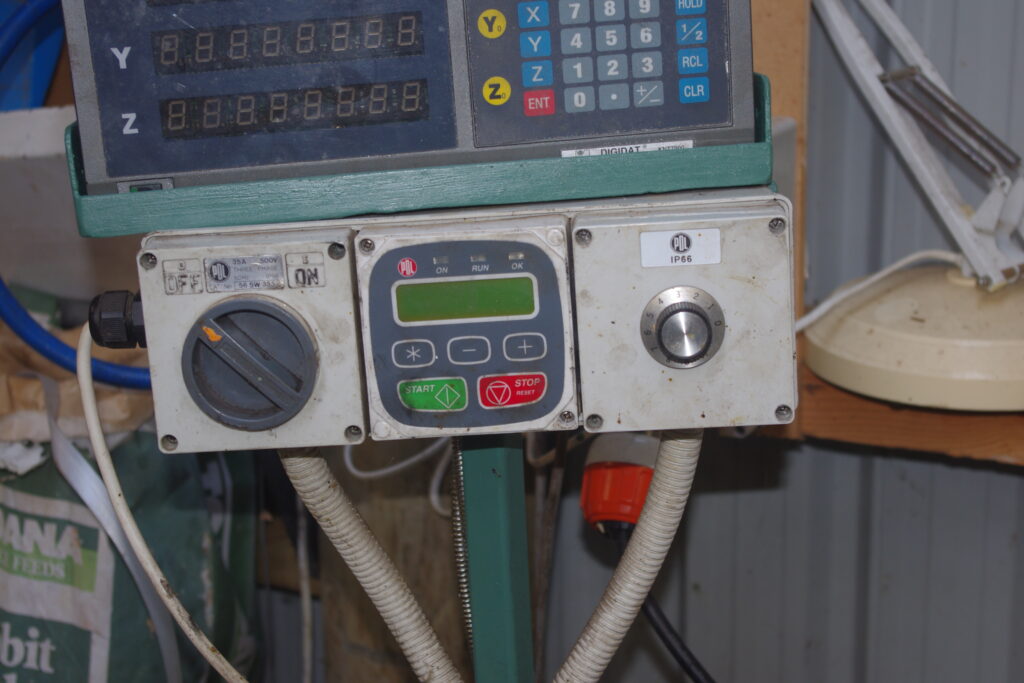
Look for a VFD with a remote-control panel, as it gives the flexibility in the mounting location while still having the drive out of the way.
I find the rotary knob is the easiest way to adjust the speed. It is a 10k Ohm potentiometer which is wired into the control terminals of the VFD, which are set up for this purpose. You may need to adjust the programming to tell the VFD to set the speed based on the external signal, rather than the internal fixed settings.
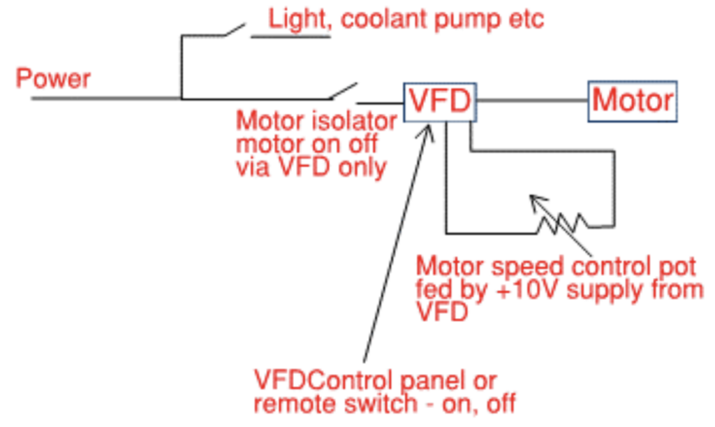
Switching
A key point with VFDs is the motor is controlled with the VFD and there is no switch between the VFD and the motor. Switching between the VFD and the motor will lead to power spikes that will damage the VFD.
Ancillary equipment (lights, relays, pumps) come off before the VFD, so it is running on the unmodified power supply. Watch out how the machine is switched inside the machine control or electrical cabinet. If it uses contactor relays – rather than direct switching for start, run, and emergency stop – you will need to rewire this so they are bypassed. At the very least ensure they are not between the VFD and the motor, with the relays or their switches providing low-voltage signals to the VFD terminals. Read the instruction manual very carefully and double check the wiring and connections, as putting 230V into a 10V signal terminal will not end well.