Getting to grips with bench power supply
By Mark Beckett
Photographs: Mark Beckett
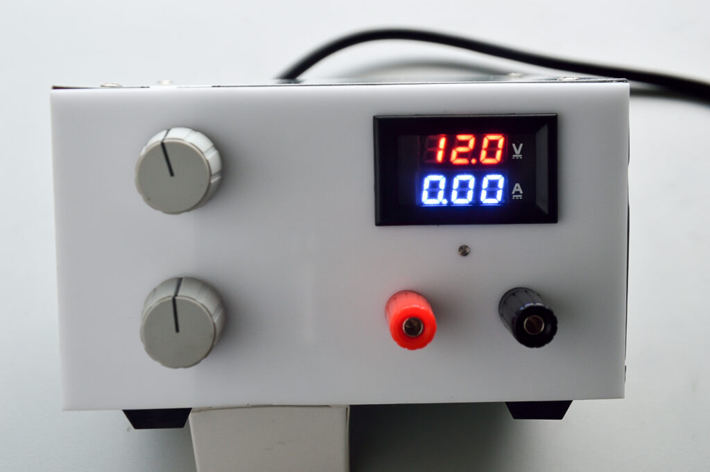
Everyone who dabbles with electronics or even automotive stuff will eventually find a bench power supply very handy. When I first started getting into electronics, they were large, expensive beasts, and very much out of the reach of hobbyists. There were a few kitsets provided by some electronic parts suppliers, but these tended to be limited in voltage and current.
If a hobbyist wanted an affordable adjustable supply, they usually had to make it. We even resorted to designing and making our own when I worked for Telecom. Commercial units were available but they didn’t suit our requirements, or budget.
In those early days digital electronics was reserved for computers and the like. We were starting to see some digital devices, but generally all power supplies were linear. They had a transformer and rectifier, and the smoothed DC was fed through an adjustable ‘loss device’ to produce a stable output.
Since the input voltage was fixed, the lower the output voltage, the greater the ‘loss’. The ‘loss’ was dissipated as heat, and they either had a fan or large heat sinks out the rear. The mains transformers for these supplies need to handle maximum volts x Amps and consequently they are a reasonable size and weight.
Switch mode
Switch-mode supplies are commonplace now and they do not require a mains transformer or large heat sinks.
They operate by rectifying the input voltage and then use a high-frequency circuit to generate the output voltage.
Because they control the input side to the oscillator, they don’t have to ‘lose’ anything to have a stable output. The higher input voltage and frequency helps reduce the transformer size and the efficiency is improved which saves power.
Most mobile phone chargers are a switch-mode variety and one added advantage is they will work from 90v-230v AC, meaning you just need a plug adaptor to take it away on holiday.
Performance
The more you spend, the better the specifications, and power supplies are no different. Commercial units have very low ripple (where the output voltage varies) and have better response when the load changes suddenly (overshoot or undershoot).
Higher-priced units tend to have much better protection against short circuits, failures, and reverse voltage, along with tighter tolerances.
In any power supply, the control circuit detects a small change via a sense resistor and then amplifies it to compensate. Sometimes that can cause instability and so power supply design is a compromise between control speed, stability and response.
I have a couple of ‘homemade’ supplies; one is 12v at 25A and was used to service a product we supported. The other is a published design and is capable of 30v at 5A.
While both of these are useful, I wanted to test something I had just repaired and needed to limit the current (to minimise damage in case it wasn’t repaired). Neither of my existing supplies had that capability.
I belong to the element14 community
(www.element14.com/community) and one of our members, John Wiltrout, had been shopping on the Asian websites when he spotted an adjustable DC-DC converter:
http://www.banggood.com/DC-DC-Step-Down-Adjustable-Power-Supply-Module-p-969200.html
This unit is a 7-40v DC Input and adjustable from 1.25 to 35v at 0.3 to 10A.
For a few dollars more it would have been nice to have a controlled fan outlet that they suggest is needed above 65°C.
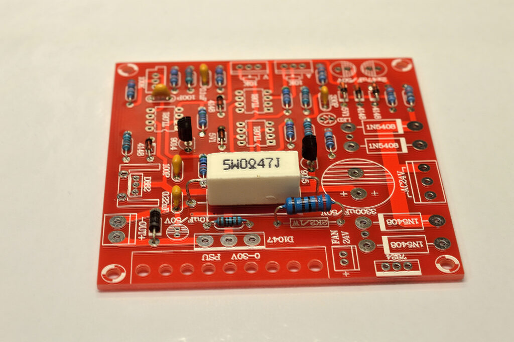
The other unit he brought was a linear kitset:
http://www.banggood.com/0-30V-2mA-3A-Adjustable-DC-Regulated-Power-Supply-DIY-Kit-p-958308.html
The input is 24v AC (max) with an output of 0 to 30vDC at 2mA to 3A.
It’s been designed to use as a bench supply and they supply a plug and socket to remotely mount the control potentiometers.
It does have a separate regulator for a 24v fan (but no control) and very good assembly and set-up instructions (which only work if you read them).
Both require you to provide the transformer, heat sink, case, and meter (plus rectifier for the switch-mode unit).
Transformers
Due to the change to switch-mode supplies, it is becoming harder to source transformers. You could recycle some, but luckily element14 carry Toroidal versions at a reasonable price.
http://nz.element14.com/multicomp/mcta080-12/transformer-toroidal-2-x-12v-80va/dp/9532706
http://nz.element14.com/multicomp/mcta300-30/transformer-toroidal-2-x-30v-300va/dp/9530932
The first link shows an 80VA 2x12v at 3.3A transformer. This has two windings on the secondary which each supply 12v at 3.3A. Wired in series, they will give me 24v at 3.3A.
The second link is a 300VA 2x30v at 5A transformer. With the two windings in parallel, it will give me 30v at 10A.
Best of all, both of these are ‘panel mount’, meaning they have all the hardware to bolt them down, and are reasonably priced.
“Sometimes that can cause instability and so power supply design is a compromise between control speed, stability and response”
Current meter
Most adjustable bench supplies need a voltage and current meter to see what you have across the output terminals BEFORE you connect your device and release that magic smoke. I still use a good-quality meter if I want an accurate voltage.
Voltage meters usually need a series resistor to limit the voltage applied to the delicate movement, while the current meters have a large shunt (a low resistance) that they detect the voltage across. Both need to be sized to suit your meter and usually the face needs recalibrating to suit the new purpose.
Once again our Asian friends have simplified the problem by producing digital meters at cheap prices.
I chose this version which is 0-100v and 0-10A:
https://www.banggood.com/Dual-Red-Blue-LED-Digital-Voltmeter-Ammeter-Panel-Volt-Gauge-Meter-p-918687.html
I had reservations about the accuracy, but testing showed them no worse than using a conventional meter, and they even have adjustment screws.
Case solution
When I first embarked on this I ordered two linear and two switch-mode boards. My thinking was to have dual power supplies in one box, but the reality is I very seldom need dual supplies, and so I decided that holding a spare of each was a much more sensible idea.
Due to the large transformer being out of stock (after I ordered it), I decided to make a single 0-30v at 3A supply. When the transformer turns up, I will make a separate 24v 10A supply.
I’ve made cases before, but I no longer have access to the bender we used. So the quest was on for a solution that would suit me and our readers.
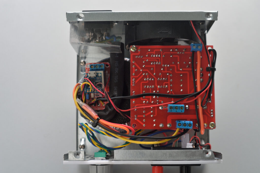
It struck me that old computer hardware may provide a cheap solution. I eventually settled on an old computer power supply that was destined for landfill or scrap. The advantage of this was it had the power socket, mains switch and a fan already fitted on the rear panel. Some of the capacitors had bulged and leaked, but the heat sink would be useful.
The quick mock-up showed that I need to be creative to fit the toroid and board in, along with a new front panel, but otherwise it should all work.
Winding transformers
I’m familiar with winding normal transformers: you wind the wires around a plastic bobbin, then slide metal, E- shaped laminations around the bobbin. The laminations are bolted together and then a coat of varnish stops them vibrating.
Toroidals are wound around a donut-shaped, iron-rich core, and it puzzled us how it is done commercially.
A few clicks of the mouse found this video:
https://www.youtube.com/watch?v=82PpCzM2CUg
Fan control
Both of the modules mentioned need a fan when they are running at full load. I prefer to have fans run only when they need to and therefore some sort of detection and control was required.
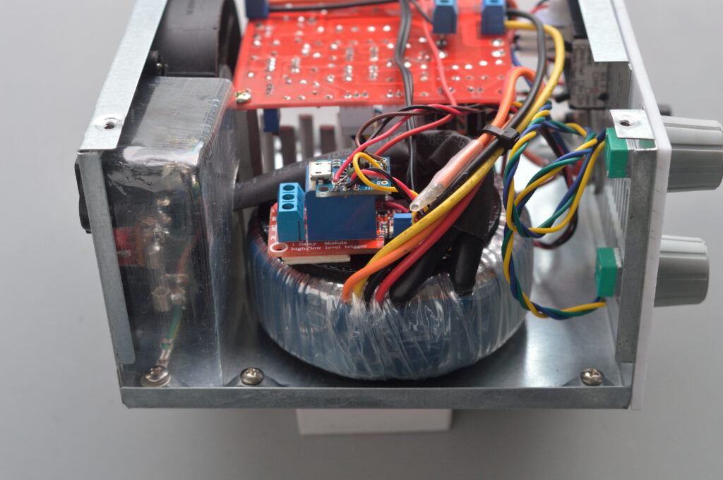
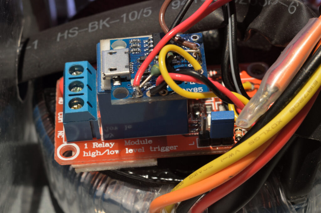
In the end I decided to make a universal design using some DS18B20 temperature sensors and an Arduino to control the fan. I set a hysteresis so that it cycled correctly.
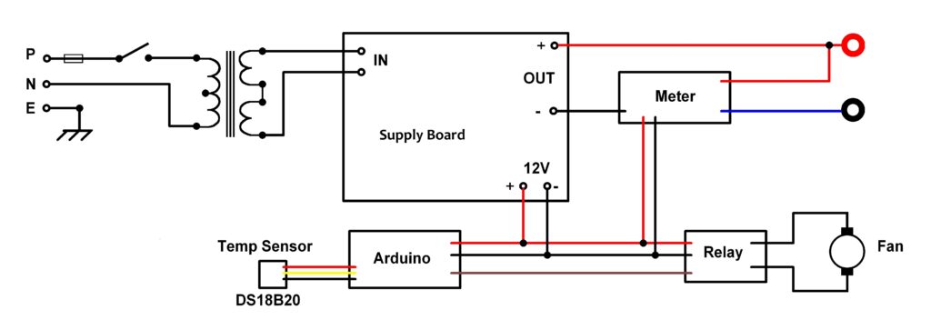
The 24v regulator on the linear supply was swapped for a 12v version and this powers both the Arduino and the fan which gets switched by an opto-coupled relay.
The sketch detects all the one-wire devices and will look for the highest temperature from all the devices.
At 45°C it will switch the fan ON, and at 30°C it will switch it OFF.
These setting are in Line 50 and 51:
int HighTempOn = 45; // High Temperature On setting
int HighTempOff = 30; // High Temperature Off setting
The code for this is available to download at the very end of this post.
You need to use an Arduino that has an on-board regulator to accept 12v. I ended up using a Digispark copy and the code is provided as well as an Arduino.
Construction
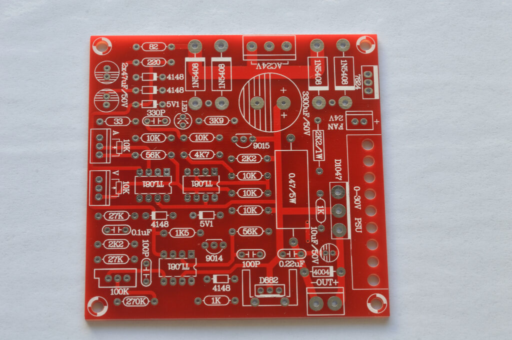
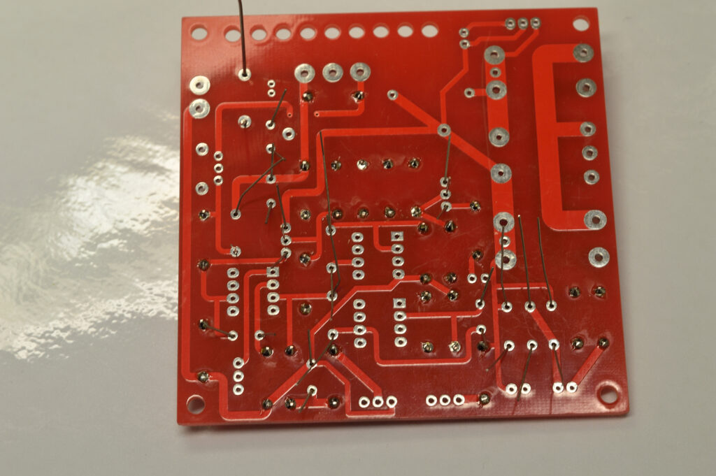
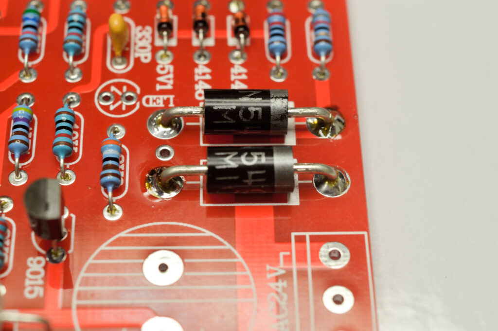
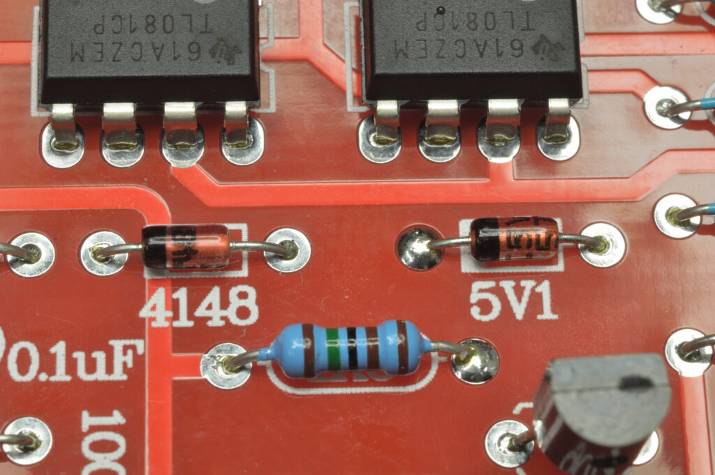
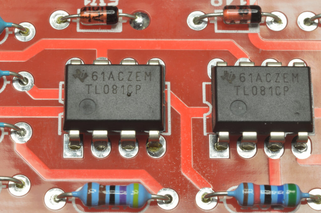
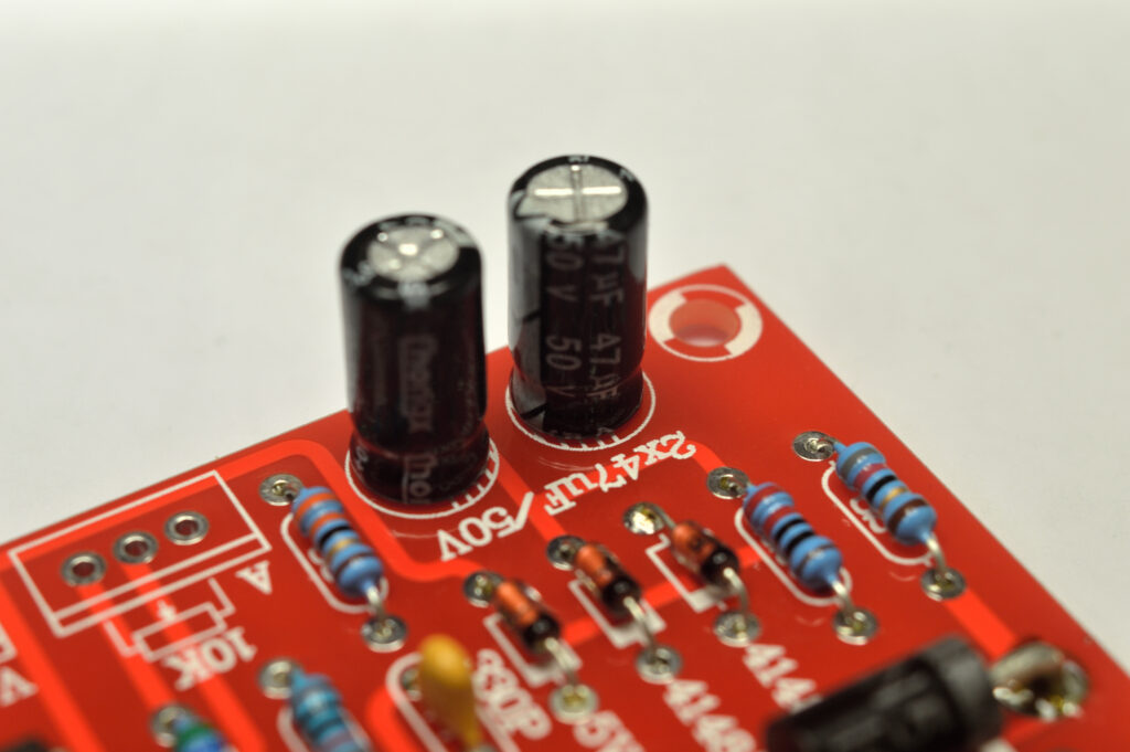
Through the magic of digital cameras, the photos show the kit and the completed unit. It is rather self explanatory and there is a good construction guide provided online by the supplier.
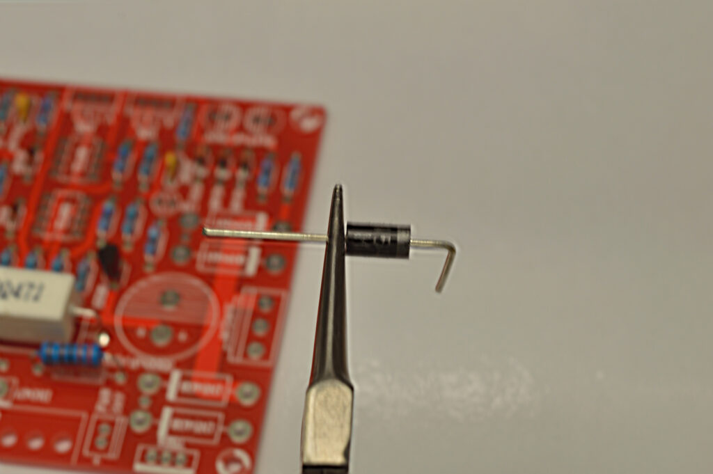
For the diodes it is always advisable to hold the lead beside the body and bend the rest of the wire. This prevents straining the fragile junction inside the body.
The 0.47 ohm 5W resistor is best stood off the board to allow airflow around the whole resistor. I’ve seen enough scorched boards to know they get warm and toasty.
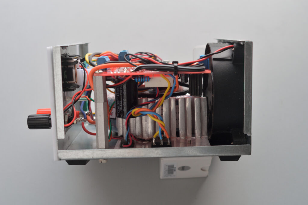
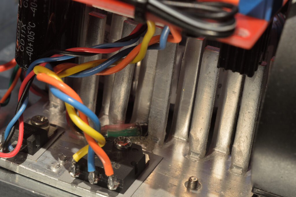
They have left a space on the PCB for a heat sink, but the reality is yours will not be the same size, so before soldering the output ‘loss’ transistor, marked D1047 (actually a 2SD1047), it’s a good idea to sort out your heat sink and PCB mounting arrangements.
Due to the case size, I had to be a little creative and mount the board upside down. I decided to run wires between the transistor and the board, and the same for the 7812 regulator.
The D1047 doesn’t require bushes or insulating washers if the heat sink is isolated, but heat sink paste between it and the heat sink surface during final assembly is always a good idea. The regulator does require insulating from the heat sink. A salvaged bush and thermal pad were re-used and both were screwed to the heat sink fitted onto the bottom of the case.
The input and output connectors were mounted on the bottom of the board (now uppermost) for easier connection. I also chose to extend the LED which shows when it is in current limit mode.
“I’ve seen enough scorched boards to know they get warm and toasty”
Board check
At this point checking that your board works might save a headache later. It requires AC to power other parts of the circuit, so find a power pack that provides 12-19 AC at 100mA. Connect this to the input and check the output voltage can be controlled along with the current.
The +ve output goes to the red binding post and the large red wire of the meter is joined to it.
The –ve output goes to the large black meter wire, while the blue goes to the black binding post.
The current detector shunt is in the negative lead wiring, hence the strange arrangement.
The cut-out for the meter measures 45×25.5 mm and the retainer is a strange design. You remove the electronics, fit the bezel into the cut-out, and refit the electronics.
These meters require external power if the voltage drops below 4.5v, so connect the small red and black wires to the 12v regulator with the fan and Arduino.
It does pay to think about your front panel layout and how far the items will protrude into the case as you lay out your design and before mounting everything. The ‘measure twice and cut once’ rule has some relevance here.
The fan will suck out air, but first it needs some air to come into the case. I elected to drill holes in the sides rather than the bottom. Some rubber feet on the bottom and it’s almost ready.
Mains wiring
As always when dealing with mains voltages, safety is paramount. Heat sink over the exposed terminals is a good idea and, depending on your construction, a plastic cover over the mains socket and switch will also prevent accidental contact. This can be light plastic or mylar but, whatever you do, add a label about removing power before opening.
The original supply had the mains fuse on the board, so I added a fuse between the socket and switch. In some sockets they are integral, so check yours before adding another.
The label on the side of the transformer shows the colours of the windings BUT, more importantly, it shows their relationship to each other.
We are connecting the two primary windings in series and the two 12v secondary windings need to also be in series. In this case, connect the bottom of the upper winding to the top of the lower winding.
You need to connect the socket earth to the chassis. Don’t skimp here as it provides protection if the chassis becomes live. If you are unsure get someone competent to check your connections before applying power.
Front panel and testing
Since the front of the case was a collection of slots, it required a front panel and I was unsure of which way to go with this. I could have used either aluminium, or a white plastic, and in the end the plastic won.
Once I was happy with it, I glued it on and with the pots and binding post providing additional fixing. It shouldn’t require screws.
I always have some trepidation when I power something for the first time. Unless I’ve tested each component prior to assembly, there is always that moment of doubt. If you’ve tested the board as described above, most of the rest is wiring errors.
I suggest using your ohm meter to ensure that there are no Phase to Neutral shorts, or short to earth.
You can repeat the test for the output ensuring both +ve and –ve have no continuity to chassis.
Obviously, you should do a full safety check and tag it, or find someone who is happy to do one for you. Remember, though, you will need to provide a label for voltage and wattage or current.
Once you’re happy, power it up. I was always taught to look away when you flick the switch. Be sure the case is ON and you’re not standing over the item.
You will require some form of meter to test the output voltage and current control. You should be able to verify that you can control the output voltage with no load connected. A 12v 21W brake light lamp makes a good 2 Amp load to test the current meter and the limit control works.
If my other transformer arrives, I’ll try to provide some images and notes, but in the meantime enjoy something that you’ve been able to craft yourself.
Phone chargers
The modern mobile phone charger is a switch-mode supply that has components that age, so leaving them plugged in while not using them simply accelerates when they will die and is a potential fire hazard.
Unplug them when you aren’t using them.
					console.log( Pin connections

  P0 =
  P1 = Relay 1 (HIGH = ON)
  P2 =
  P3 =
  P4 =
  P5 = DS18B20

    DS18B20 Pinout (Left to Right, pins down, flat side toward you)
    - Left   = Ground
    - Center = Signal (Pin 2):  (with 3.3K to 4.7K resistor to +5 or 3.3 )
    - Right  = +5 or +3.3 V

     DS18B20 Temperature chip on pin P5
     4k7 pullup between pin P5 and +5v.

     Created 19 Apr 2017
     by Mark Beckett

     based on the code here http://forum.arduino.cc/index.php?topic=72654.msg546490#msg546490

     */

  #include <OneWire.h>
  // Use P2 to avoid issues with clones
  #define DS18B20_PIN 2                   // DS18B20 is on P2 (Clone Digisparks being sold have P5 as the reset as they have the wrong fuse settings)

  // DS18B20 Temperature chip i/o
  OneWire ds(DS18B20_PIN);                 // TempSensor

  // maximum sensors on the bus
  #define M 5

  // actual sensors detected
  byte m = 0 ;

  // addresses
  byte addr[M][8];

  //Outputs
  const int Relay1 = 1;               // Relay 1 Output

  //Settings
  int Highest = 0;                     // Highest of all sensors.
  int HighTempOn = 45;                 // High Temperature On setting
  int HighTempOff = 30;                // High Temperature Off setting

  //-------------------------------------------------------------------------

  void setup_tempsense ()
  {
   m = 0 ;
   while (ds.search (addr[m]))
   {
      if (OneWire::crc8 (addr[m], 7) != addr[m][7])
      {
        return ;
      }
      if (addr[m][0] != 0x28)
      {
        return ;
      }
      m++ ;
    }
    ds.reset_search () ;
  }

  // asynchrounous start conversion
  int start_conversion (byte i)
  {

    ds.reset () ;
    ds.select (addr[i]) ;
    ds.write (0x44) ;         // start conversion, with parasite power on at the end
  }

  // asynchrounous read result
  int read_conversion_result (byte i)
  {
    byte present = ds.reset () ;
    ds.select (addr[i]) ;
    ds.write (0xBE) ;         // Read Scratchpad

    byte data[9];
    for (byte i = 0 ; i < 9 ; i++)           // we need 9 bytes
    {
      data[i] = ds.read();
    }
    int temp = (data [1] << 8) | data[0] ;   // just want temperature
    return temp ;
  }


  // synchronous call to read temperature from one sensor
  int read_temp (byte i)
  {
    start_conversion (i) ;
    delay (800) ;     // maybe 750ms is enough, maybe not
    return read_conversion_result (i) ;
  }


  void setup ()
  {
    //Define the pins
    pinMode(Relay1, OUTPUT);
    digitalWrite (Relay1, LOW);    //Relay is OFF
    delay (500) ;

    setup_tempsense () ;

  }

  void loop ()
  {
    // start all the conversions
    for (byte i = 0 ; i < m ; i++)
    {
      start_conversion (i) ;
    }
    // share the wait
    delay (750) ;
    // read all the results
    for (byte i = 0 ; i < m ; i++)
    {
      //Serial.print ("dev ") ;
      //show_id (i) ;
      int temp = read_conversion_result (i) ;
      float centigrade = ((float) temp) * 0.0625 ;

      if(centigrade > Highest)
      {
        Highest = centigrade;
      }

    }

    RelayControl();
    Highest = 0;            //reset the reading at each trip thru the sensors.
    delay (250) ;
  }

  void RelayControl()
  {
       //Relays are ON when the output pin is HIGH

       if (Highest >= HighTempOn)                              //reading is above or equal to the setting
       {
         digitalWrite(Relay1,HIGH);
       }

       if (Highest <= HighTempOff)                              //reading is below or equal to the setting
       {
         digitalWrite(Relay1,LOW);
       }

  }
  );


