The Shed Logo
Search
Close this search box.

Build your own smoothing plane

Here is an outline for making a small steel and brass smoothing plane which looks similar in style and size to the common Stanley or Record No 3 size. There the similarities end. The main differences are the blade is 5mm thick, it has a screw blade-adjuster but no back iron or chip-breaker. The screw-type cap is bronze and massive. The sole is 8mm thick and dovetailed to the 6mm thick brass sides. The knob is a refined version of the Stanley but the rear handle is a more radical departure. There is no frog. The blade is solidly bedded on a steel bridging piece which connects the sides to enhance rigidity and houses the swivelling adjuster mechanism, allowing for lateral adjustment of the blade.

An expert shows how a first-class plane comes together
By Philip Marcou
 

Here is an outline for making a small steel and brass smoothing plane which looks similar in style and size to the common Stanley or Record No 3 size. There the similarities end.
The main differences are the blade is 5mm thick, it has a screw blade-adjuster but no back iron or chip-breaker. The screw-type cap is bronze and massive. The sole is 8mm thick and dovetailed to the 6mm thick brass sides. The knob is a refined version of the Stanley but the rear handle is a more radical departure. There is no frog. The blade is solidly bedded on a steel bridging piece which connects the sides to enhance rigidity and houses the swivelling adjuster mechanism, allowing for lateral adjustment of the blade.

Machining the dovetails on a mill
Trial fit of sole and sides

Works better
The sides are also united by the cross-pin which engages with the cap to keep the blade set on the bed without movement or chattering. The cross-pin is riveted flush to the sides and the bed bridging piece is screwed flush to the sides. All dovetails are air-tight – seamless in other words. These are the main differences which result in a plane that not only looks good but also works far better than the common type.
I like to use gauge plate for the sole because this is supplied accurately ground and straight. It is not liable to distort when further machined or worked. for the sides, I prefer to use one of the harder brass alloys. The blade is made from D2 tool steel which is best heat-treated by a specialist firm. Local hard timbers such as puriri and black maire are good choices for the knob and handle.

Dovetails housed
A perfect fit

Tools
When it comes to tools required, Honourable Members of the File and Hacksaw Brigade will have a field day, but I prefer to at least have a mill drill and a bench lathe. Good eyesight is useful but vision enhancement in the form of head loupes etc is necessary at times. Life is dull without digital calipers.
Other machines such as disc sanders and a belt grinder save a lot of bother. A bandsaw that can run at speeds suitable for cutting wood steel and non ferrous is highly desirable. Oh, I almost forgot: you must beg, borrow or steal a surface grinder.
As far as basic machinist work this is not difficult, even for woodworms like me: it is merely a number of steps which get easier with practice and use of initiative. Anyone can make an error and a good fix is one that is not evident, does not weaken anything and may even result in an improvement in design. If you have learned to peen metal and can do basic turning, then most mistakes can be banished. Good luck.

Reaming hole for the knob

First step
Assuming you have transferred a “working drawing” from the cerebral melting pot to a scrap of paper, the first step is to cut the gauge plate (a.k.a. O1 tool steel) with bandsaw and refine it to the final dimension. It pays to be precise here, otherwise small discrepancies compound themselves at each successive step. You can either mill it or use the surface grinder.
The next thing to do is to dimension the brass for the sides. Leave them rectangular, i.e. not shaped, and they should be an exact pair. The dovetails need to be scribed on the sides with the aid of marking blue. Be sure that you have a wide socket at the mouth area, otherwise the sole will be cut in two pieces when you cut the mouth slot.
Cut the tails by removing the bulk of the material with bandsaw then milling the pair with a dovetail cutter in the mill. Once this is done, those tails are the reference for the joint and the sole must be made to fit them and not vice versa – or at least that is my method, and it has yet to lead to either failure or a loss of temper.

Plane sides temporarily joined, rough cut ready for linishing
Linishing the sides on a self-built linisher

Sole
Now to the sole: use each side to mark out the joint with a scriber onto the blued area. Use whatever means suits to remove the waste: it could be with a CNC or Bridgeport machine, with chain drilling and filing or a combination if you only have a small mill. The objective is to have the sides a tight fit to the sole.
If you are doing the traditional double-flare dovetails then the flare can be filed by hand at this stage. It is preferable to avoid double flares if you are using hard brass. You merely leave them square and find another method of ensuring that they can’t come out the same way that they went in. I use tapered pins set into holes drilled and reamed at an angle off vertical. Be sure to allow for peening…be sure to allow for peening…be sure to allow for peening…
The next step is to machine a slot for the mouth in the sole using the mill, or drills and files if you must suffer a near-death experience. Ditto for the ramp in the sole. The ramp is easily done by milling, provided you have a means to hold the sole at the correct angle, 45° in this case. I use a pair of purpose-made steel wedges in the machine vice for this.

Plane side pieces linished to shape
Sole, sides and cross pin

Accurate measure
At this stage, take an accurate measurement of the inner width of the sole so that you can then turn the shouldered cross-pin for the cap and make the steel bridge bed to the same length. You might as well turn out the following in mild steel at this stage as well:
* two shouldered screws to attach the sides to the bed. These fit into counter-bored holes in the sides. They will be proud until you have peened them, then they will be ground flush;
* one screw similar to the above to be used to fix the sole to the knob carrier via a counter-bored hole in the sole; and
* one knob carrier.
Drill and counter-bore the sides for the bed-connecting screws, and drill the sides for the cross-pin. Make these tapered holes so that you can rivet this to the sides. The positioning of these holes is crucial.
Next make the shouldered brass base that locates the handle and fix this to the sole by use of counter-sunk machine screws. Fit it and then remove it. It will go back on permanently with Locktite later when the plane is assembled and you drill the hole for the handle-fixing rod.

Partly assembled planes in production. Note the cross pin and the adjuster mechanism
Plane blade

Sides
Now you can get excited because all you have to do is to cut the profile of the sides (again do them as a pair) and refine them with belt grinder. Then you can assemble the sides to the sole, being sure to include the cross-pin and screw the steel bed through the sides. Ensure that this component is at the correct angle in relation to the ramp! Then you can peen all proud edges at the dovetails and the screw heads, mill them all flush and there is the crude plane.
It is all downhill from here and not really possible to make any life-threatening errors. The brass base of the adjuster needs to be turned to the correct height so that it is in the same, er, plane as the ramp. This component has a stub that fits into the hole that you did not forget to drill in the steel-bed bridge piece –  so that it can swivel. It is also drilled and threaded to accept the adjuster stem.
The adjuster stem itself is threaded at the rear for  a brass knurled knob, and at the front it has a turned shoulder for the adjuster peg which engages with the blade. It is useful to have the blade on hand when you are making the components for the adjuster.

The front knob, screw cap and the rear handle and its threaded rod connector. Note the post on the plane is for the front knob
Screw adjuster mechanism

Bronze cap
The next major component is the bronze cap, which will be bandsawn to rough shape then refined by milling, then drilled and threaded for the cap screw. This needs to be robust and a nice smooth fit in the threads of the cap.
Then you can do some woodwork for the knob and handle, and some careful drilling for that angled hole through the length of the handle. The hole needs to counter-bored for a nice brass slotted nut at the top. If you value your finger tips it is advisable to devise a safe means to hold that handle when routing the profile or you will suffer the use of files, rasps and much sandpaper.
The knob, too, needs to be bored to accept the knob carrier stud, plus a counter-bore at the top for another nice brass nut, this time shouldered and without a slot. Now is the time to drill and thread the angled hole in the brass base under the handle. This is done with the base fitted to the sole. If the thread continues into but not through the sole it will be much stronger.
The remaining part is the best part – the surface grinding of the sole and sides. Be sure to grind the sole square to the ramp (it is not a skew-mouth plane) and to the sides, otherwise those who use shooting boards will complain. Check that the sole is flat and lap it to be sure. Hone your blade and there you go.

Blade cap (close-up)
The screw cap and adjuster mechanism on a finished plane

Philip Marcou
Cabinetmaker Philip Marcou can trace his interest in modifying and making planes exactly to the point  here he bought a Lee Valley & Veritas No 62 ½ plane and a 4 ½ smoother. To suit his tastes and his needs he modified the handles and the way the cap and knob were fixed. He was hooked and admits on his website that, from his knife-making experience, he understood the  seductive power of working  with fine wood, brass and steel. Because he liked the plane he decided he would make a plane himself, using double dovetails. As a long-time member of the Knots Forum of the American Fine Woodworking magazine, he explored what members wanted in planes. He was inspired by the workmanship of Karl Holtey’s classic hand planes and has developed his own style. Several years ago, Marcou emigrated from Zimbabwe where he ran his own successful woodworking business for 12 years and continues to make fine furniture in his Waihi workshop here.

Philip Marcou with a newly finished plane

Share:

More Posts

Refurbishing my bench plane

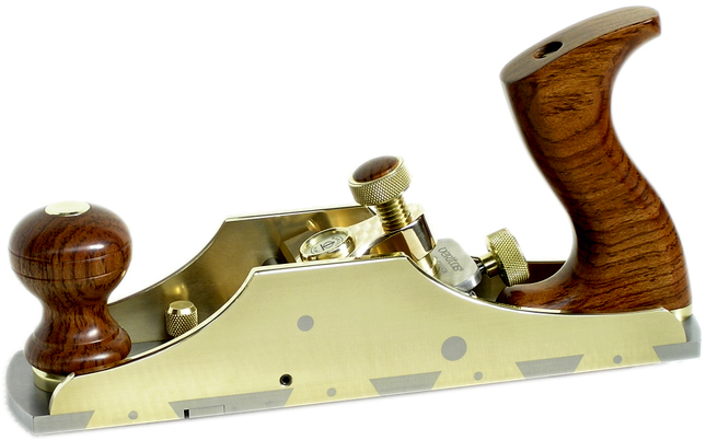
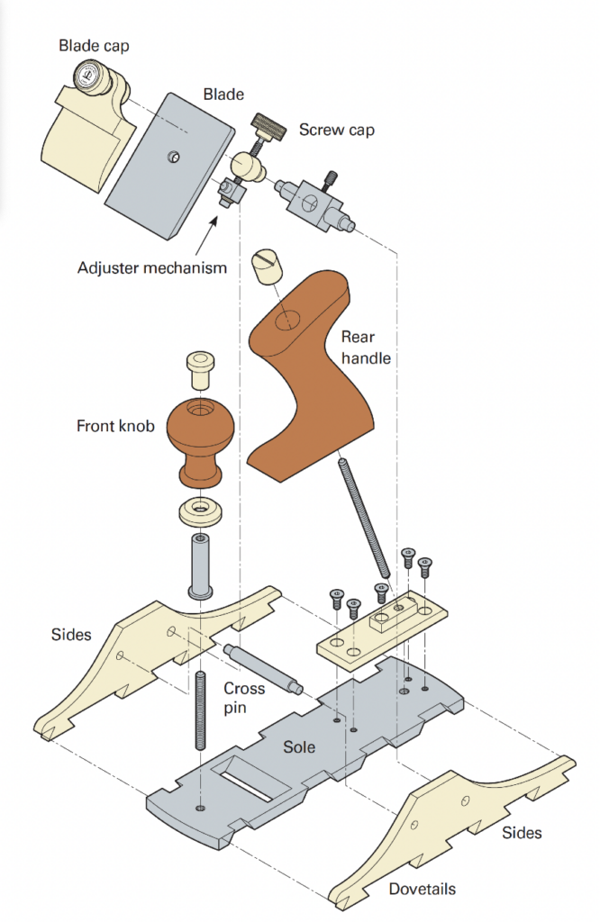
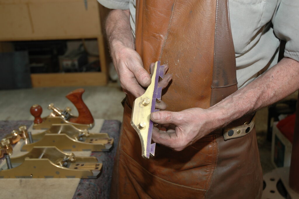
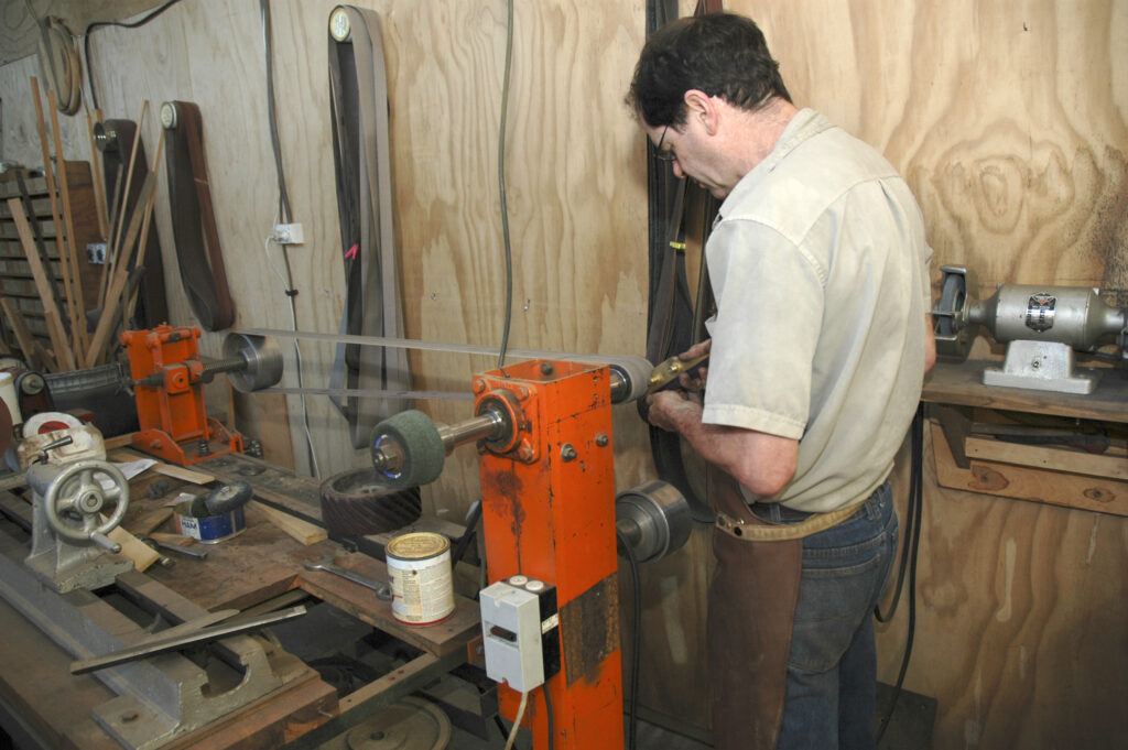
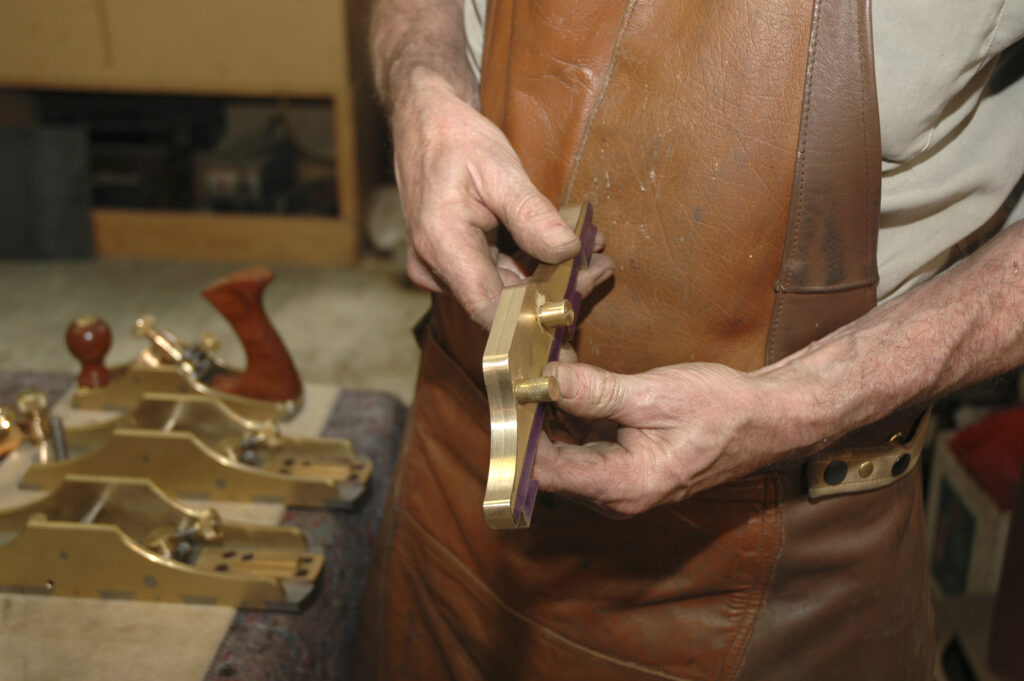
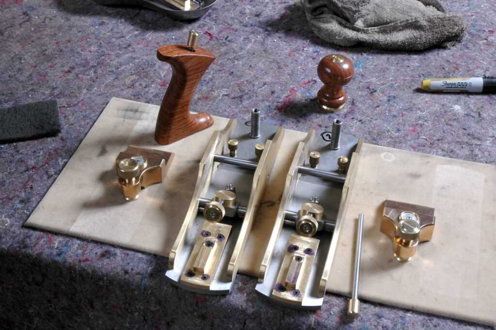
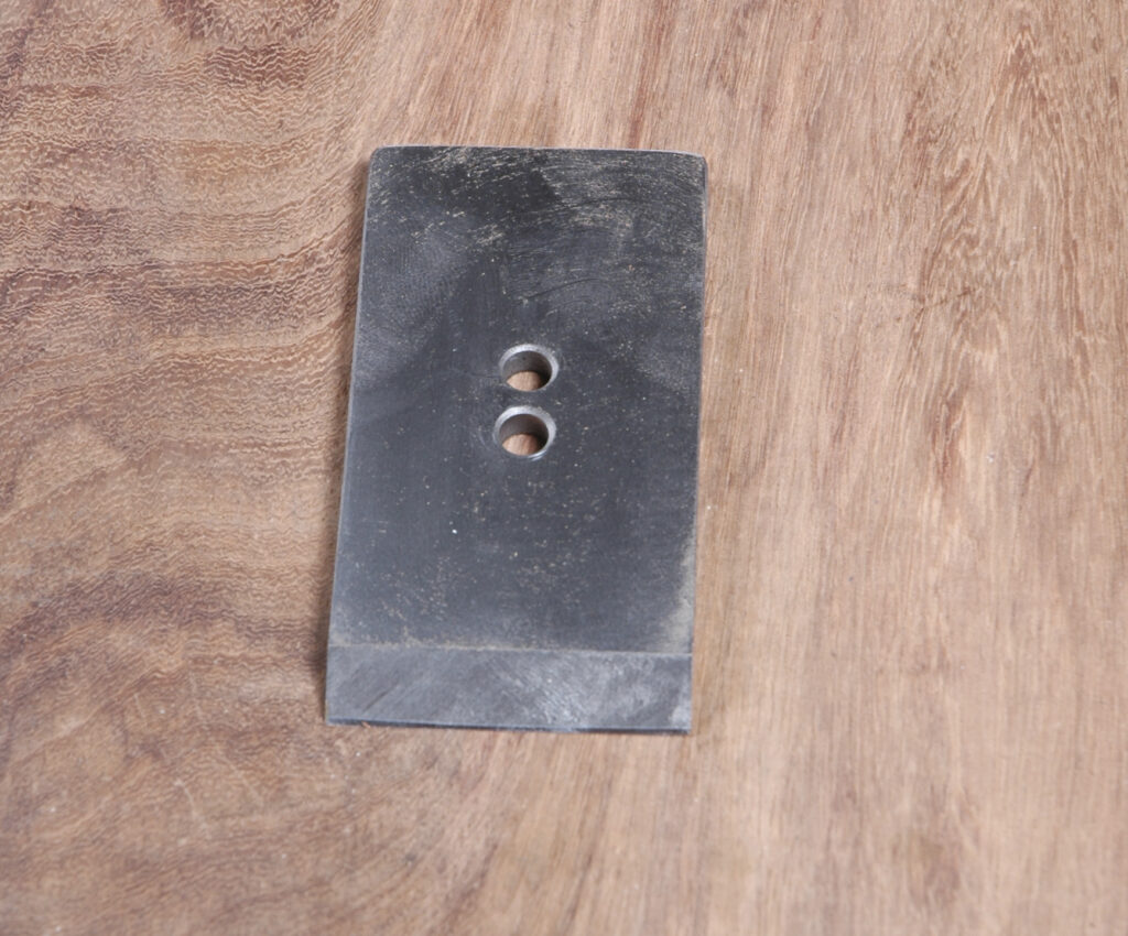
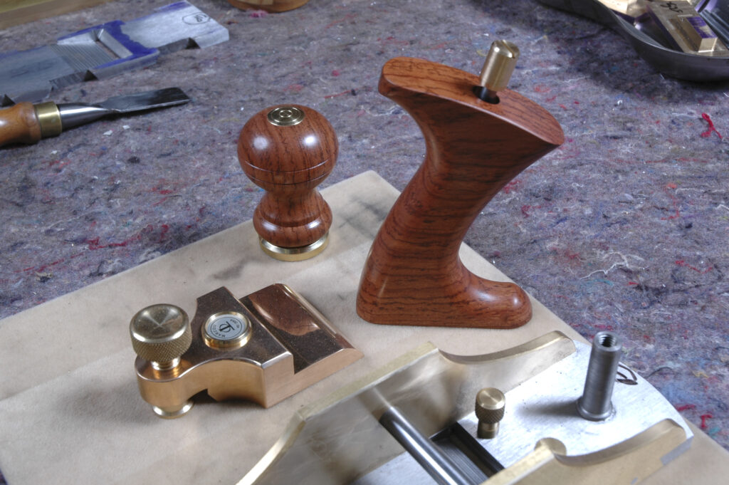
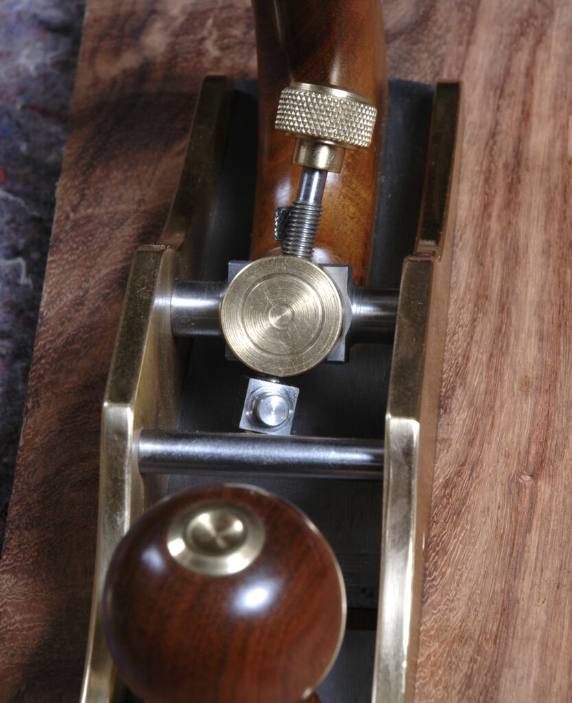
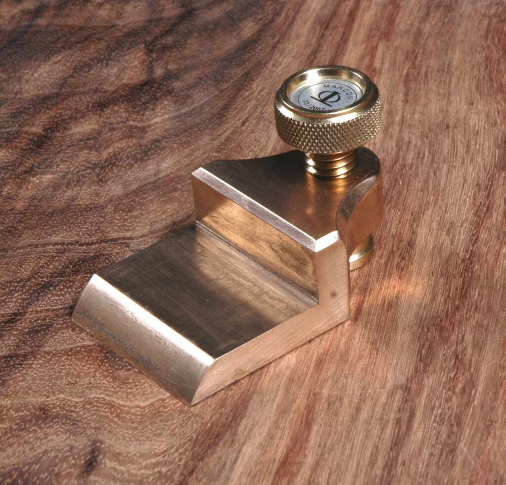
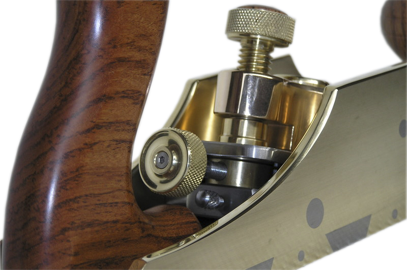
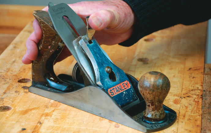
The metal-based hand plane must be one of the most enduring and useful tools in the kit of any aspiring woodworker.
Those of us who take the hobby a little more seriously will have several of them and we will probably argue that we use them all. I have six or seven but have never bought one.