Microcontrollers and robots are everywhere – why not experiment with your own?
By Chris Draper and Andrew Wells

Remember Meccano?
Many of us grew up with the Meccano® construction outfi ts, and we would hazard a guess that most have also borrowed parts to prototype something-or-other.
Today’s kids are more likely to have a bucket of Lego®, but for something with the mechanical needs of our industrial robot model, Meccano is still the better choice. Meccano was invented and patented in 1901 by Frank Hornby (of the model train fame, (although Meccano came fi rst) as “Mechanics Made Easy.” The name is thought to derive from the phrase “Make and Know”.
Over more than a century, ownership of the company and the marque has changed many times from Triang Toys to Airfi x Toys, French accountants and the Japanese toymaker Nikko (2000). Meccano is currently made in France and China. Despite several changes in colours, materials and specifi cations, Meccano has a constant that has remained since the beginning: the Imperial measurements for the ½ inch perforation spacing of the holes and the 5/32 inch nut and bolt threads.
Once the desire of every schoolboy, Meccano is alive and well and available in a range of sets (outfi ts in Meccano-speak), from reputable toy and hobby stores. There is also a good supply of used Meccano on TradeMe and EBay, and individual spare parts are available from specialist mail/internet suppliers such as Auckland-based www.meccparts.com – who have supplied the parts for this project, including the special motor mount brackets.
Build your own robot
Robotic toys are on the must-have list for many a Christmas.
The car industry for one would not run without robotic welders and painters, and this has been the case
for more than 40 years.
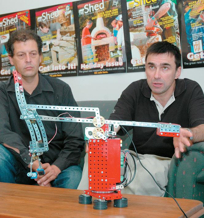
This article is all about building your own Meccano version of a robot that can be programmed to work just like the big fellas – and you can learn just how challenging real-world robots are to control. The robot arm can be programmed to move small objects from one place to another. It can reach, grab, lift and swivel. These movements can be put together in an infinite number of sequences and therein lies the value of robot arms. They can be programmed to do any repetitive sequence as complex as you like, and hence the value of this arm as a teaching tool.
There is a trade-off between cost and precision in any mechanical system, so our choice of Meccano will give us a “fast track” but at the cost of accuracy. This robot arm design is biased for simplicity and functionality, not aesthetics, and is ideal for learning or demonstrating basic principles.
Stacking toy blocks is an ideal starting point with this arm, and a programme designed to complete the
famous ‘Tower of Hanoi’ has been successfully run on our model. A full program that reads a table of movement instructions and executes them for the robot arm is available for download along with many other examples for the Motorvator at the manufacturer’s website at www.meccanisms. com. If you have chosen to use an alternative unit – all is not lost– the supplied program is so easy to follow you should be able to adapt
the logic to whatever you have chosen to use.
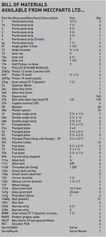
What do I need?
A complete list of the Meccano pieces we have used is provided in the bill of materials but few are critical. You can substitute whatever you have on hand – even making your own parts from sheet aluminium if you desire.
Getting good-quality small DC motors with integral gearboxes is a perennial problem for robot experimenters. In this project, we have used units imported by Meccparts.com, but you can substitute alternatives sourced new or second-hand from places such as Surplustronics.
We have used the MotorVator™ – a versatile New Zealand-made microcontroller that can be used
to control small DC motors, radio-controlled type servo motors, and relays. It can also sense the world
via digital and analogue sensor inputs. This unit comes with its own PC-based programme development
environment that is very easy to learn and so is ideally suited to our training application. But feel free to
use another similarly capable unit – or even build your own.
There are some good microcontroller experimenters books available that have circuits that could be adapted
for use here, but that would be a whole project all of its own. The programmable microcontroller we chose is built into the robot body for extra strength and the plan will also need some experimentation should you decide to use another unit.
How does it work?
The programmable microcontroller can sense the position of the joints such as the arm or wrist (axis of movement in robotic-speak), via a special sensor that emits a series of pulses when the joint is
moving.
The microcontroller issues a command to the joints motor to start moving, listens for the pulses from the sensor, counts them, and determines when the joint has moved enough then turns the motor off. This type of sensing is called “relative position” sensing. Its accuracy relies on each position being correct based on the previous position, as in a traditional treasure map. Here, precision comes from the careful execution of one step after another, such as “two paces east, then five paces west”.
Industrial robots typically use “absolute position” sensing, akin to giving our pirates an absolute position with longitude and latitude for the buried treasure. But absolute sensors are expensive and require
precise setup (and pirates didn’t have GPS…). We’ve opted for a combination of relative sensing, and a home position for each movement. In the operation of the robot arm, we start off by taking each movement
to its home position, then counting the pulses from there – just like the pirates.
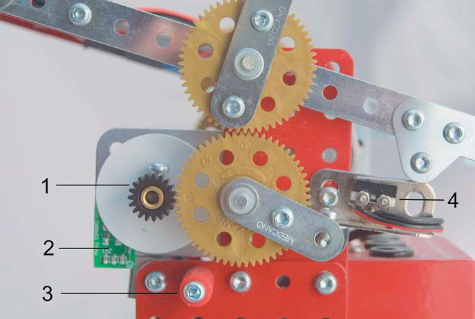
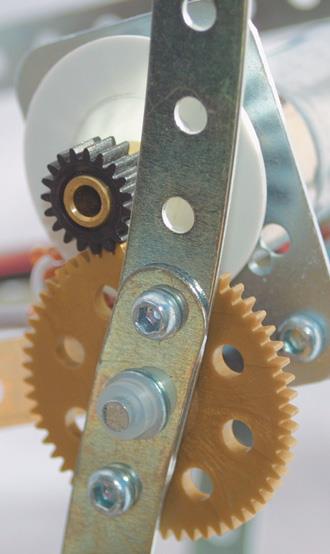
Referring to the close-up photo of the wrist mechanism, you can see:
1) the rotation sensor gear, 2) the rotation sensor pcb, 3) the stop-pin at extreme extension, 4) the microswitch controller used to detect Home position.
Control of the hand-grab is simplified by using a Futaba ServoMotor – familiar to any radio control hobbyist. These have a built-in feedback mechanism, so they can be instructed to move to any position within a 180-degree range and they will hold that position. A wide range of ServoMotors is available, with the larger ones used for mainsail winches on radio-controlled yachts offering several kg/cm of torque.
These units are a robot experimenter’s friend
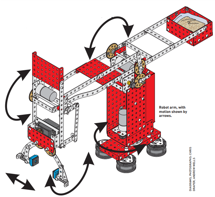
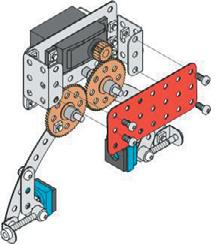
Assembly required
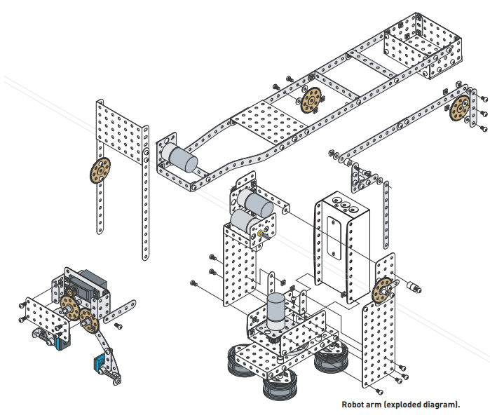
The exploded-view diagrams accompanying this article show how all the parts come together. While the robot arm looks complicated, is really very simple — pieces held together with shafts, nuts and bolts
in the true Meccano tradition.
You should have no problems working carefully from the diagrams and the additional notes. If you get stuck, Meccanisms has online help at their website where you can ask the experts. The forum section already has blow-by-blow instructions and diagrams for this arm.
Note that Meccano part numbers are quoted frequently, both for those familiar with such things, but also as the most expedient way of cross-referencing the accompanying parts list. Please check out www. meccparts.com online catalogue as each part carries a colour picture which will be useful if you are unfamiliar with the Meccano parts and their numbers.
The arm can be broken down into three major sub-assemblies:
The base, including the turntable joint, and upright section which contains the microcontroller.
The arm, which mounts on the top of the base and includes the counterweight, arm joint on the top of the base, and the motor/ joint assemblies for the shoulder and wrist.
The hand which mounts on the wrist.
The base
The rotation turntable is made up of two Meccano No 19B pulleys separated by a set of 3/8 inch balls (Meccano still uses Imperial measurements) and uses a No 137 wheel flange as a ballrace. The
centre axle is fixed to the base with a bush wheel. A 19-tooth pinion fitted to the motor shaft runs around the 57-tooth gear wheel fixed to the axle. Note that this plan uses Meccanisms 40rpm gear motors
– these have compact internal gearboxes that minimise the need for extra gearing to achieve the required speed and torque for each movement.
The MotorVator can control any DC motor requiring 3-12V voltage and a maximum 1.5Amp current, so other motors could be used with appropriate gearing. The superstructure relies on the MotorVator microcontroller
for strength. For you Meccano buffs – the MotorVator is the exact footprint of Meccano Part No 52, so fits into many Meccano models with ease.
The arm
The arm is roughly counterbalanced about a standard axle, and the motor drives onto a 57- tooth gear wheel fixed to the arm, via a 1:9 reduction.
The plan uses an idler modified from a plastic 57-tooth gear wheel and a 19-tooth pinion pinned together. A more traditional solution could use a standard 19-tooth and 57-tooth pair fixed to a freely rotating shaft. The
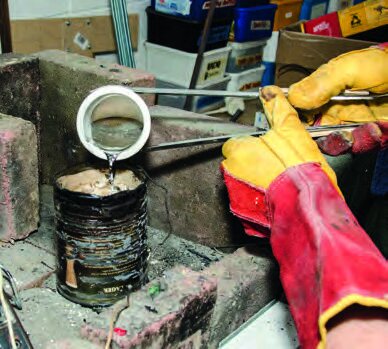
large, square box-counterweight can be filled with bagged sand, ball bearings, shot, lead, or whatever you
have on hand that does the job.
The shoulder joint again uses a simple 19-tooth pinion running around a fixed 57-tooth gear wheel. The wrist cock is built in the same way, but via a parallelogram and bellcrank arrangement to maintain a fixed wrist-to-ground angle regardless of the shoulder angle.
The hand
The hand is constructed using a model aircraft-type servo unit that has been modified to turn
a standard Meccano pinion. The pinion engages with a gear fixed to one arm, which is also engaged with an identical gear on the other arm – thus opening and closing both fingers at the same time.
The fingers are also spring-loaded so they can provide a surprising amount of grip.
Position detection
Detecting the home position of each movement is important, so in most cases, we’ve used microswitches to
detect one extreme of movement.
In the case of the shoulder and wrist we’ve economised (and simplified the wiring) by instead putting a dead-stop and writing code in our program that detects when the movement has stalled on this dead-stop. This works for our model because the geared motors we’ve used can be stalled without damage. Depending on your choice of motor, you may not be able to do this; we originally used a more
powerful motor on one of these movements and it happily tore the links apart rather than stalling.
Use counterbalancing to work within the limitations of the motors and Meccano system. A bag of sand or handful of nails in the hopper opposite the arm makes everything work more smoothly and saves having to screw the base to the table.
Balanced movements also keep the speeds similar in each direction – otherwise, the arm will race down but grind up.
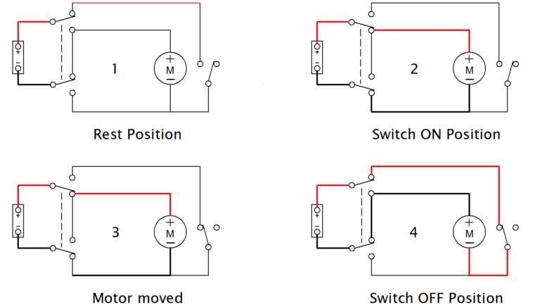
Wiring your unit
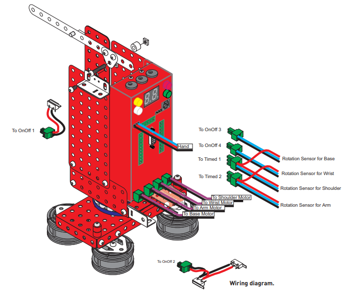
Each motor and sensor is wired back to the appropriate port on the microcontroller, (see wiring diagram). The wiring is straightforward, and as you can see there are three groups of cables – one lot for the motors, one lot for the rotation sensors, and a final group for the limit switches (used to help the robot find its known starting point for counting from).
If you find it more convenient to swap some of the motors or a sensor around – it’s a simple program change to match. The maximum single-motor current is under 0.5Amp, so light, flexible wire can be used. Stick to multi-stranded wire, as the wires will be flexed continually during operation. For our combination
of microcontroller and motors, a single power supply of 12V DC at 1.5Amp was sufficient. If you are
using different motors, calculate the amperage required by adding the total current requirement of all motors that might run concurrently, and add a bit for a safety margin.
Testing your unit
Don’t let the apparent complexity of a microcontroller intimidate you. These units are performing pretty dumb steps, (albeit rather quickly), and each step can be logically tested to ensure it works as intended. Some of this testing should be done before the whole robot is assembled – for example, the hand can be built, plugged into the microcontroller, and worked – making it easier to fix any binding or misalignment problems.
The sample program includes a routine to test each movement individually, by the simple method of repeatedly moving each movement in one direction by a fixed number of pulses, then in the reverse direction by the same number.
Programming
Once each movement can be controlled in this way, programming a realistic sequence of movements is just a case of stringing together individual movements. Once sequential movements are mastered, concurrent movements can be readily programmed, at which point the arm really comes alive.
Limitations of space have prevented us from delving into the big subject of programming. but the following gives you a taste of how it’s done:
The Motorvator unit we have used has its own BASIC_ like language and responds to commands such as
SetMotor 1,”F”,80 which translates to “Set motor One to forward direction at 80% of full speed”.
As mentioned, the details for programming including the complete program for this arm are available at www.meccanisms.com.
And finally
I would suggest the editor would love to hear from anyone who builds this arm as-is or some adaptation. This has been a tremendously enjoyable project, and I hope all who choose to do something similar and have half as much fun as we have getting this little arm to run through its moves.