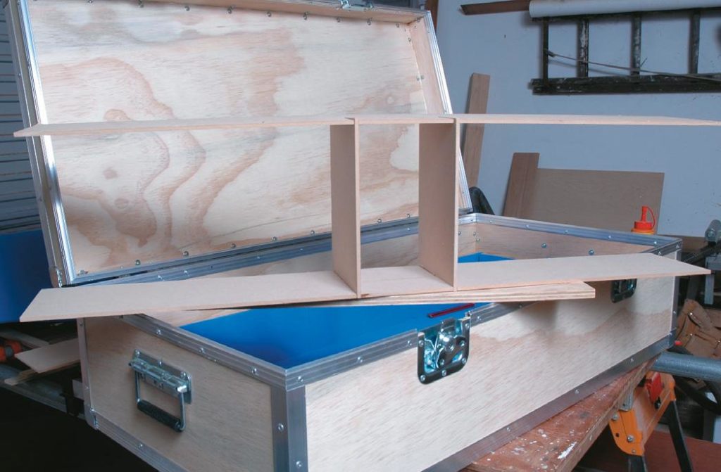
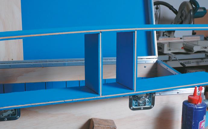
Then there is the relatively new kid on the block: the ARF (Almost Ready to Fly) model.
These come all packaged up in a huge box, beautifully built and packed, with all the hardware. But you do need to assemble them which can take up to a week. It isn’t quite ‘instant plane’ but it does provide some building satisfaction and a sense of achievement, albeit a rather shallow one, a bit like a healthy walk down to the bakery to buy a pie or taking Viagra.
To the supplied kit, you need to add various glues, an engine and electrical components (servos, relays, wires) to operate elevator, rudder, ailerons, throttle, flaps, undercarriage etc. The engine these days could be glow plug, 4-stroke or 2-stroke, electric or petrol.
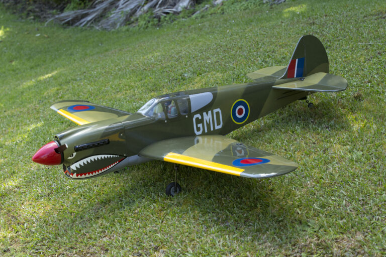
This part of the hobby is now huge and the range and quality of products is astounding. ARF aircraft kits are readily available from many hobby shops and certainly online from within New Zealand and from lands far away.
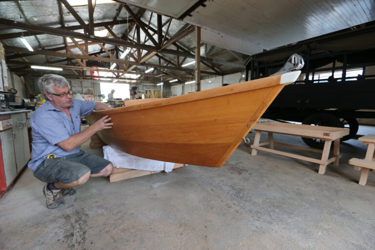
Piopio in the heart of the King Country – a landlocked area with a village population of about 400 – is the last place you’d expect to find a boat builder. Boat builder Max Laver, however, is well settled there and business is thriving.
Boat repairs, restoration, and making small craft by hand is the speciality of Max’s business, where he works with fibreglass and timber, and specialises in custom-built dinghies.
“We focus on how well we can make a dinghy, not how cheaply,” he says.
Max is a marine surveyor as well as a boat builder.
He spent two years in Lowestoft in England learning City and Guild-level wooden boat building, and finished his time doing two more years learning in New Brunswick, Canada.
In 2009, after many years boat building, Max decided to study marine surveying and the two qualifications work hand in hand.
“I didn’t excel at school as a kid, but I loved to build,” he says.
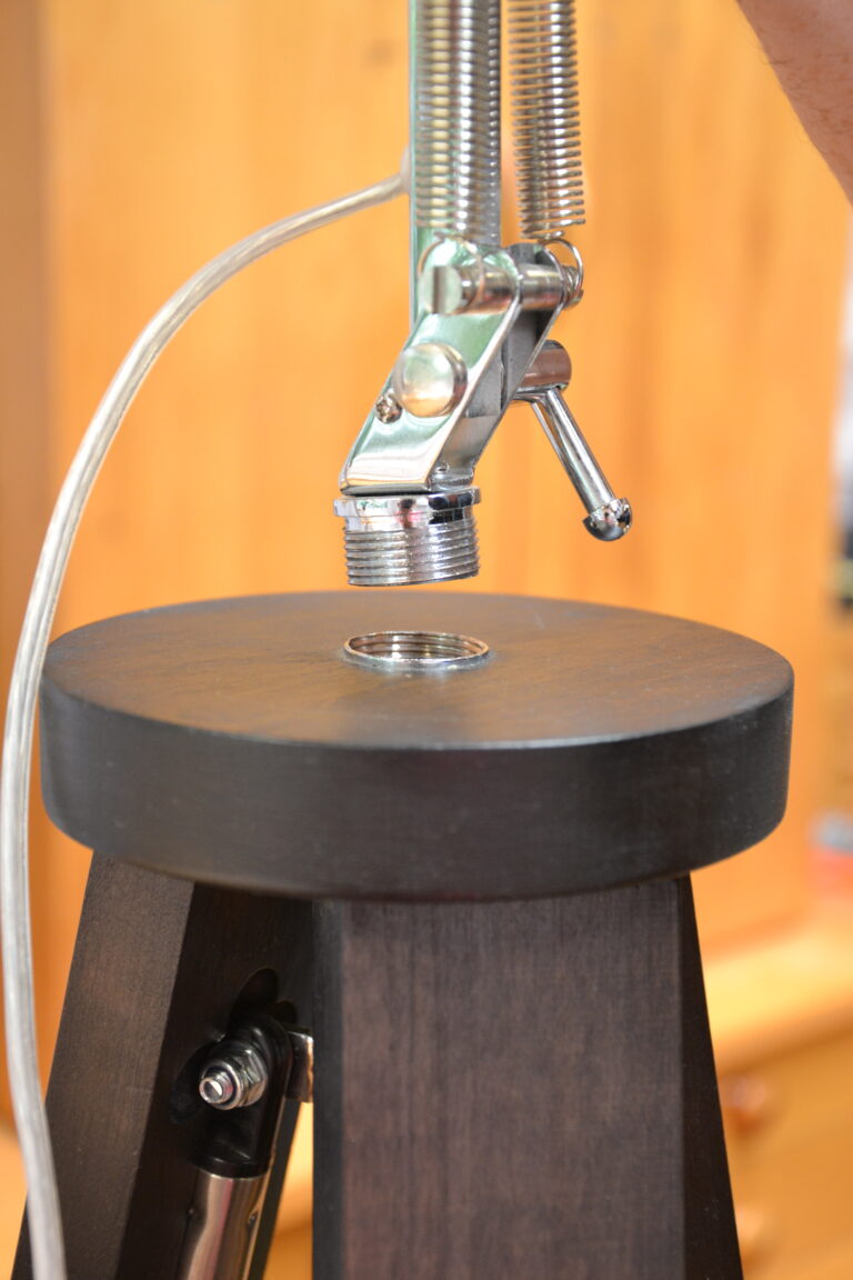
My daughter was looking for a large lamp for her husband’s birthday and struggled to find something with the modern industrial-type of look that she had in mind. She asked me if I could make something around her thinking. She particularly wanted a large tripod base with an adjustable lamp on the top.
We searched around for a suitable lamp for the top and found an adjustable lamp on a spindle base at Lighting Direct on sale for $89.95. We would have preferred a matt black finish but we felt the chrome model would work very well.