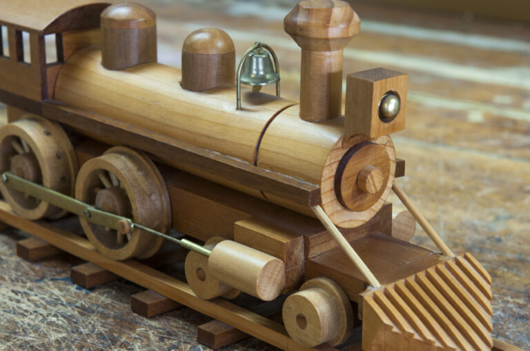
When you are a carpenter by trade with an interest in cars and still young at heart, making wooden toys has to be the perfect retirement occupation—although many of Alan Gray’s “toys” are not the sort of playthings you would put in the hands of small children. His meticulously crafted vintage vehicles, fashioned mostly from native timbers, mahogany and macrocarpa, can take around 60 hours to make and are more collectors’ pieces.
To keep the real kids happy, he has a more robust range mostly made from pinus radiata— diggers, trucks, pull-along hippos and the like.
Alan, 71, and his wife, Lesley, have been living in Cromwell for the past six years. Originally from Dunedin, Alan trained as a carpenter but turned his hand to fishing after moving to Stewart Island. He then spent the best part of three decades skippering boats for the Department of Conservation.
Save the date: Friday 20 – Sunday 22 February 2026
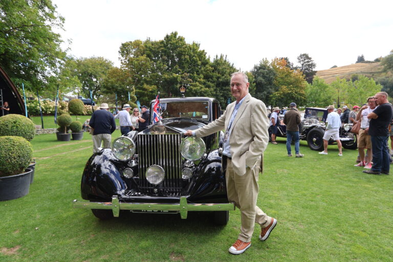
That’s right. The Ayrburn Classic returns next February for what promises to be another world-class celebration, scheduled slightly earlier on the calendar to bask in Central Otago’s long golden evenings and late-summer glow. This festival will once again transform Ayrburn into a playground for car enthusiasts, food lovers, and seekers of high-end hospitality alike.
The 2025 edition set an incredibly high benchmark, and is fast becoming one of the leading reasons to visit Queenstown – amongst New Zealanders and international travellers alike. With over 250 classic and contemporary luxury vehicles on display – collectively worth more than $250 million – the festival was a visual and visceral feast for attendees.
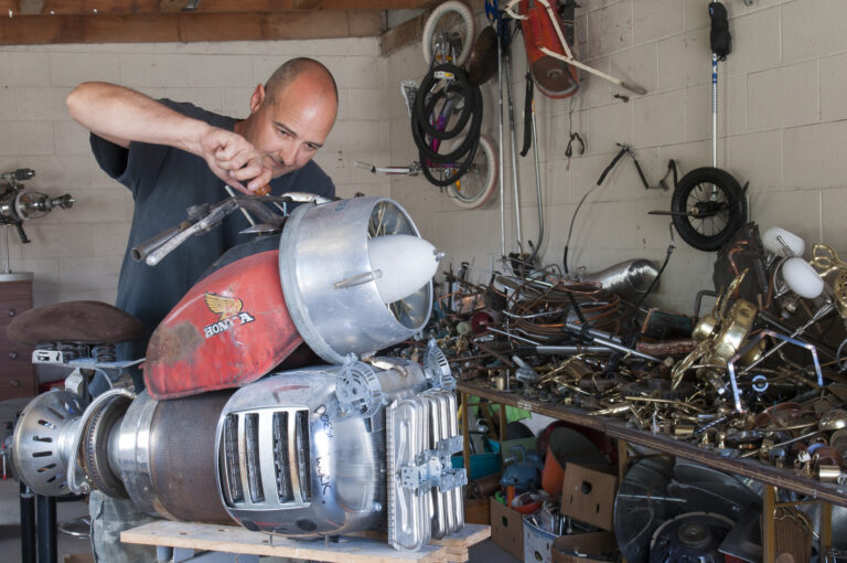
A sci-fi artist working from a backyard shed in Central Otago is turning stuff no one wants into things that are sought after across the globe.
Sean Boyd uses anything that takes his fancy, from light fittings and plumbing parts to typewriters and old vacuum cleaners, to make futuristic fabrications which include ray guns, life-sized robots, jetpacks and other cosmic curiosities.
“The satisfaction is in finding parts, imagining outcomes and working out how they can fit together,” says Sean, who gets most of his raw materials from the local recycling centre, Central Otago WasteBusters. “I fill the back of the car for about $35. I think I’ve got more waste here than the waste station,” he says, looking round at the piles of paraphernalia in his humble garage in Clyde.