Knowing the basics of hydraulics will help you to work out the best system for the job
By Ray Nielsen
Hydraulics is the science of converting one form of energy, to another, using a fluid as the transmitter.
A hydraulic circuit can be broken down into four basic components:
Prime mover
This is what gets the whole show going. Usually some form of pump.
Control system
Obviously there has to be some sort of control to tell the oil where to go, how much, and at what pressure.
Actuator
This is what is receiving the oil from the pump via the controls. Most common actuators are hydraulic cylinders, hydraulic motors and hydraulic winches.
The wet system
This is a broad term to describe all of the components that hold the oil and the paths that the oil travels through.
PRIME MOVER
Pumps
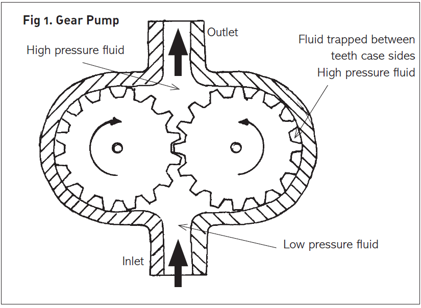
A gear pump is probably the most common type. Oil is fed into one side of the housing, picked up by the cavities formed by the teeth of the gears, and carried around the outer circumference.
It exits on the other side of the housing. (Fig 1)
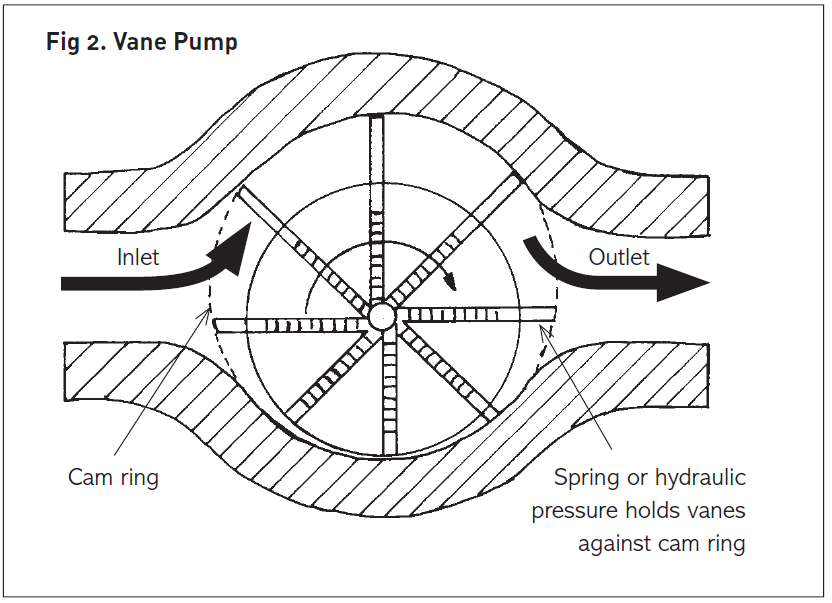
A vane pump is also a common type.
Inside a round housing, a round rotor is located off-centre. Around the circumference of this rotor
are several vanes axially fitted in machined slots. As the rotor turns, the cavities formed between the vanes on the high side are filled with oil. As the rotor continues to rotate the cavities become smaller, and the oil is compressed and exits the housing. (Fig 2)
Oil pumps can be single, (one pump, one inlet, one outlet), multi,(a series of single pumps stacked on top of each other driven by a common shaft), or staged, i.e. a multi-pump — but instead of inlet
and exit ports for each housing and gears, there is only one inlet and exit port.
There is usually a main pump and from this, the other pumps are fed by internal galleries. The exit is out of the smallest or highest pressure pump. Most pumps are fixed displacement where the total displacement of the pump is determined by the volume of oil contained within the housing,
expressed in cc per revolution.
The overall flow is determined by total rpm. The faster the shaft speed, the larger the oil flow. Most oil pumps have an optimum speed which is usually no less than 800 rpm and no more than approx 2500 rpm. Manufacturers’ data will always give you this optimum speed.
CONTROL SYSTEM
Oil flowing out of the exit port will always enter some form of control. The simplest and most
critical will always be a relief valve.
Hydraulics, especially in optimum operating conditions, are capable of producing some extremely high pressures and forces and if there were no way to bleed off the excess, the results could be catastrophic in the extreme. After the relief valve, there will then be some form of directional valve, generally a spool valve.
Spool valves come in several confi gurations; the most common are single-acting and double-acting. The single-acting has only one working port which the oil flows through to the actuator and then returns back through the same porting in the reverse position.
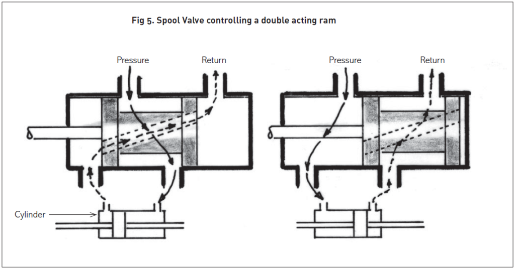
With the double-acting valve, there are two working ports: in one position, oil flows from one port to the actuator; in the other position oil flows out of the other port to the other side of the actuator.
While oil is flowing down one path to one side of the actuator, oil is also flowing from the other
side of the actuator back through the valve and to the oil tank. In the opposite extreme, the reverse happens. (Fig 5)
With the single-acting valve, this is not quite the case because there is only one path. In the working
position, the oil flows from the pump through the valve to the actuator. In the centre position, the oil is usually trapped in the actuator. In the reverse position, the oil flows back down the same path but this time a bridge is created to send the oil back to the tank.
ACTUATORS
Hydraulic cylinders come in two basic types: piston/seal and displacement.
Piston/seal
The piston type is the one that we see most. The hydraulic tube contains a piston with a polyurethane seal. This is attached to a shaft which is contained in the tube by a top gland nut and which also has a seal fitted to it. We will refer to this assembly as a “ram”.
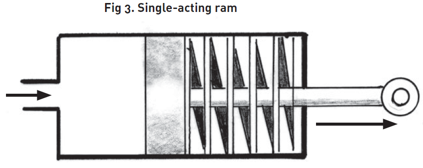
If the ram is single-acting, oil enters only one side of the piston, there will be only one entry port
(obviously on the pressure side) and a breather port on the top side (Fig 3).
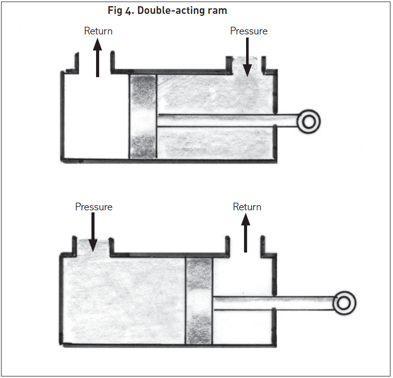
With a double-acting ram, there are two pressure ports, one above and one below the piston. As oil enters one it exits the other. (Fig 4)
DISPLACEMENT
With a displacement ram, there generally is no piston and seal, just some form of guide and a stop to prevent the shaft from coming all the way out. The shaft acts as the piston upon which the oil flow acts. Displacement rams are always single-acting and therefore there only needs to be one port (inlet) and this can be located anywhere on the tube.
The main advantage of this type of ram is that because the diameter of the shaft determines the force, a very strong ram can be obtained from a relatively small diameter cylinder. If you required
a reasonably long-stroke, small-diameter cylinder and the design allowed for the action to be one
way, a displacement ram would be the way to go.
THE WET SYSTEM
Oil pressure lines and fittings
High-pressure hose is SAE rated and will always have its pressure rating stamped or moulded on the outside. The rating is generally determined by how many rows of wire casing are wound around the outer diameter.
Hydraulic fittings come in two basic forms, reusable and crimp. The reusable ones are far more expensive than the crimp type and it takes some skill and patience to fit them, but they can be reused and you don’t need any special equipment to fit them.
The crimp type on the other hand requires special crimping equipment and fittings. Crimping is
the industry standard. The ferrule and fitting are far more compact and the final hose assembly is safer since a professional with the correct equipment has put it together.
OIL FILTERS
Cleanliness is critical to the longevity of a hydraulic system, so good-quality filtration is vital.
Return-line filters should be installed into the tank line to filter the oil on its return to the tank.
OIL COOLING
One of the biggest enemies of a hydraulic system is heat. The temperature must never be allowed
to reach 90° C. Temperature can be controlled with either a large reservoir up to three times the oil
flow, or an oil cooler.
DESIGNING THE SYSTEM
Now that you have a basic overview of some of the components that go into making up a hydraulic system, let’s take a look at a practical application. The wood splitter is a good example.
First you need to determine what you are trying to achieve. In the case of our log splitter :
* How much force is required to split the timber?
* How fast do you want to complete a full cycle i.e. ram full out and full return?
* How much horsepower is available to power the pump?
We will illustrate an example using a single-stage pump with a safety margin of 200 bar (pressure
in bar: 1 metric bar = 14.5 lb/in²).
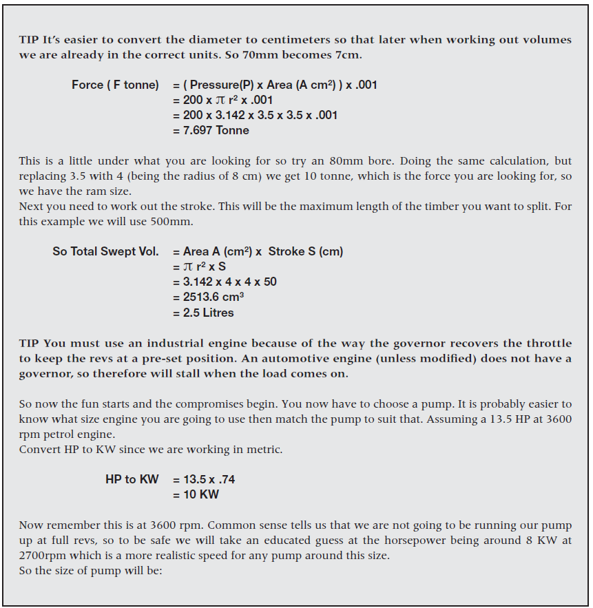
It must be emphasised that an oil pump does not pump pressure, but flow. Pressure is created by the load on the actuator. The rating of the pump determines the pressure you are going to be working with so you need to decide how much force you need. Let’s assume that ten tonne will split all of the timber you will encounter.
We must now select a ram of suffi cient diameter to deliver the force required within the pressure constraints of the pump. Let’s start with what is available off the shelf. For example, standard bore diameters in metric tube are, 32, 40, 50, 60, 70, 80, 90, 100, 120mm.
After checking the physical sizes of the rams, you feel that the 70mm (7cm) bore is going
to be pretty close, so let’s do the sums.
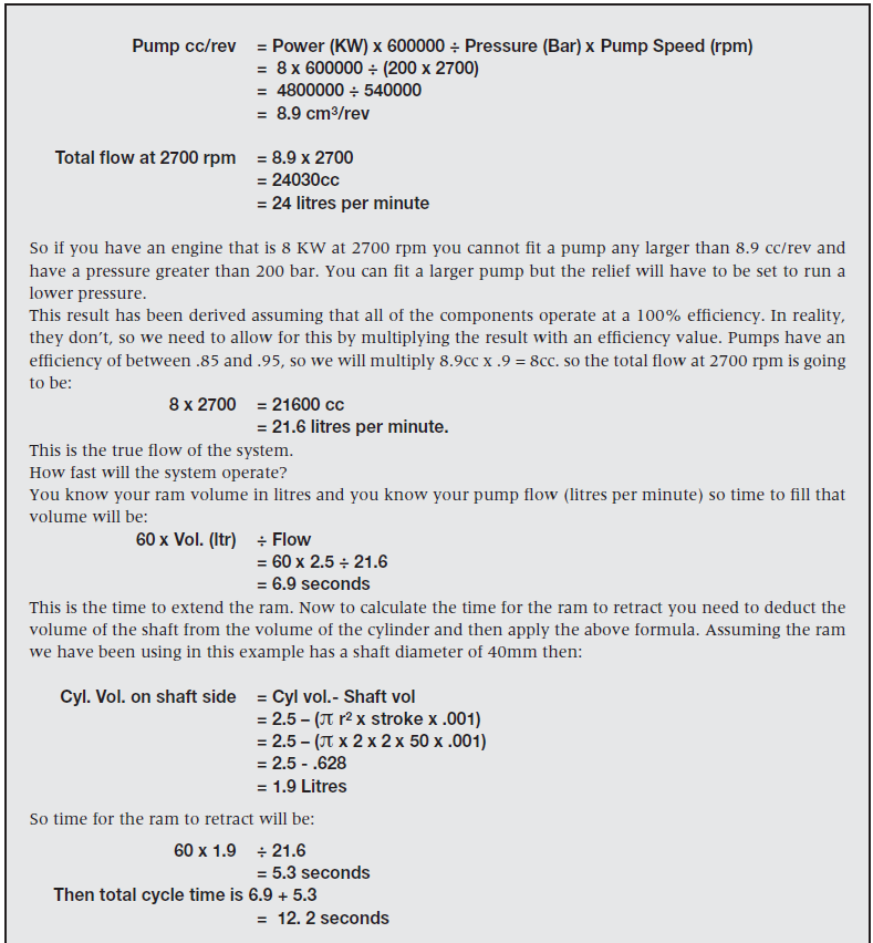
If you are happy with the results you can now complete the system with the rest of the components. Oil fl ow is going to be approx 20 litres/min so using our rule of thumb you are going to need approximately a 60-litre oil tank. This is assuming continuous operation.
For a home wood splitter with an intermittent duty cycle, you would get away with a lot less.
The next critical component is the control valve. Everything in hydraulics has a fl ow rating. We know that we have a fl ow of 20 litres/min, so providing we don’t use anything that has a fl ow rating less than this, we can choose any double-acting spool valve to suit a particular application.
In this case, you may want to use a valve that has been specifi cally built for wood splitters with an auto detent on return.
The relief valve is built into the body of the valve. With all the components assembled, all that’s left is to take it into your hose doctor or purchase a hose kit and have it plumbed. I always like to have the suction hose approximately 100 percent bigger than the pressure hose. Try to keep all of the plumbing on the larger side. This reduces friction which in turn reduces heat.
Ray Nielsen is the Managing Director of C& C Hydraulics (NZ) Ltd.