Roll-your-own is the answer to those sheet metal problems
By Gary Farquhar
Dimensions
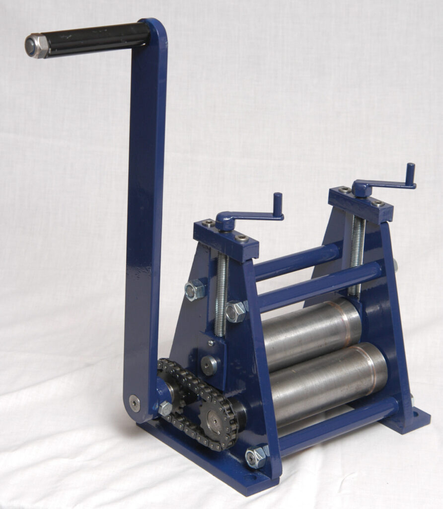
These dimensions are only a guideline as to proportions as there is no fixed size to the machine you could build.
Base width 170 mm
Height 230 mm
Width 190 mm
Centre roller gap 26 mm
Main roller shaft 24 mm
Centre roller shaft 18 mm
Handle shaft 17 mm
Sprocket shaft 21 mm
Sprocket 15 teeth (Saeco 06B1-15)
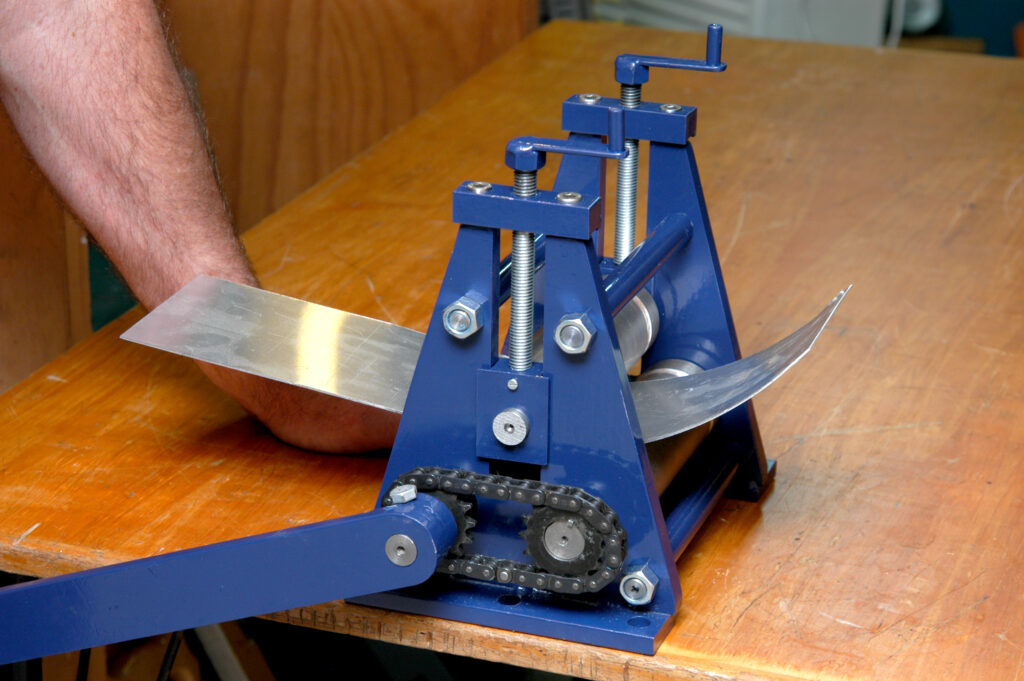
Isn’t it always the case—you are working away in the shed with the latest project and you need some equipment or tool that you don’t have? I needed to roll some metal for the model project that I am working on and I had recently lost my access to a metal-rolling machine. The best answer was to make my own sheet-metal roller. I quickly realised there were a lot more future projects needing a rolling machine.
The first design consideration was the roller configuration. There are two main configurations:
- You can have the driving rollers on top of each other and a rear, single roller as the adjusting one;
- You can have two bottom rollers which are the driving rollers placed in the same plane and a top roller as the adjustable one.
With No 1, which has the driving rollers on top of each other, you can roll tighter. This machine requires two adjustment screws, the first to nip the material and the second moves up to create the curve on your work.
However, I chose the second version with the adjustable top roller over two bottom driving rollers. My main consideration was the first option usually needs a set of interlocking gears. They have longer than usual teeth to allow for the adjustment in the nip roller. You may get away using normal gears (which I didn’t have in my “odds and ends” box).
The other advantage with the second option is you can drive the rollers by a chain-and-sprocket arrangement and it doesn’t require any adjustment
Materials
The frames are made of 12 mm mild steel plate which I had lying around in the “will-come-in-useful-some-day” pile. The rollers are made from EN8 steel bar at 50 mm round, as this is a harder material and should not get as easily marked by your work. Mild steel would also work okay if the machine is going to be used only occasionally in the shed. For the frame spacers I used 16 mm round bar. You will also need a length of 12mm mm threaded rod and some 16mm mm square steel for the top retaining brackets.
Construction
I drew up a plan in full size so that I could work out where the rollers and the frame-retaining bolts went to give clearance to the centre sliding retainer holding the third roller.
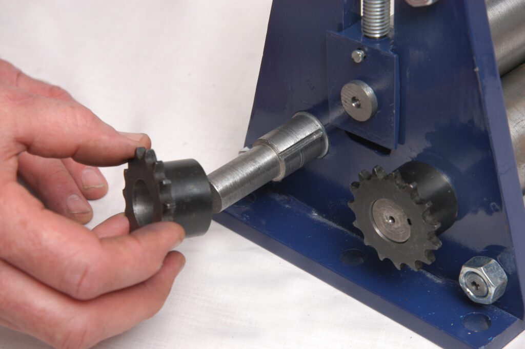
After my initial design phase, my first task was to machine down the two bottom rollers, remembering to leave one longer to accommodate the handle. I also, as this stage, bored out the sprockets to the maximum internal diameter recommended by the manufacturer so that I could get a good, solid thickness on my roller shafts. Doing this first allowed me to temporarily fit the sprockets and chain onto the rollers. That way, I could accurately measure the centres to know where to bore the holes in the frames and keep the chain at the correct tension. I have left a gap of approximately 25 mm between rollers.
Frames
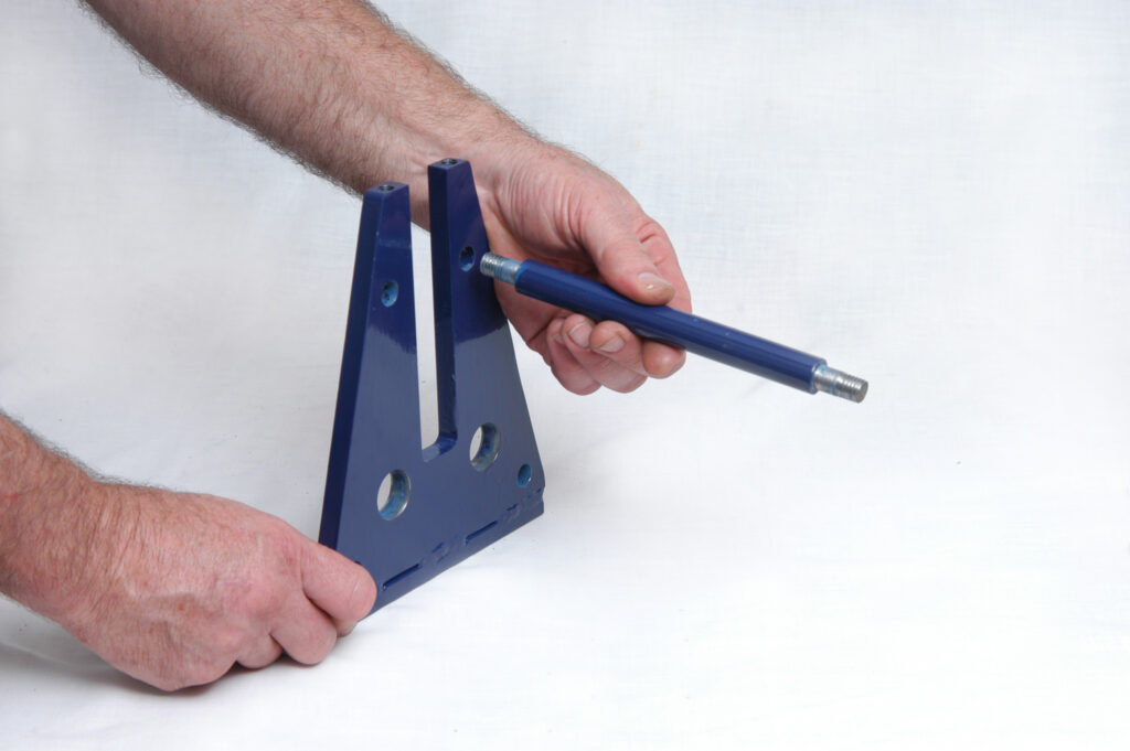
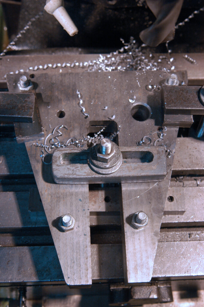
After marking out the frames, I flame-cut the outside profile, ground it with an angle grinder and tidied it up in my mill. I drilled the holes where the frame-spacers go so that I could temporarily bolt these frames together for further machining. This was to ensure that when I was cutting out holes for the centre and two bottom rollers, they would be parallel
For the centre cut-out in each frame wall, I drilled a series of holes along the bottom then set the sides in a power hacksaw and cut down the two lengths. (You could use an angle grinder with a cutoff wheel.) This quickly removed the bulk of the material before I set it up in the mill to clean up the sides and bottom. I also welded on some feet so I could bolt the sheetmetal roller onto a bench. I may in the future make a pedestal for it to stand on.
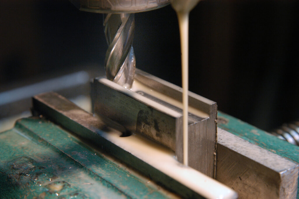
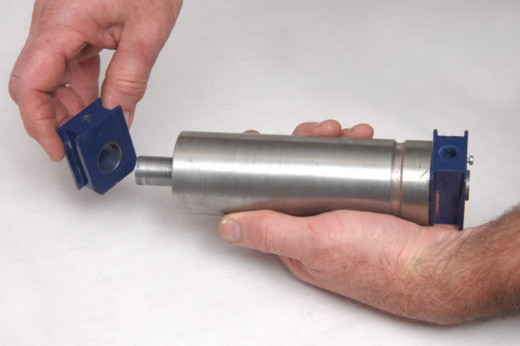
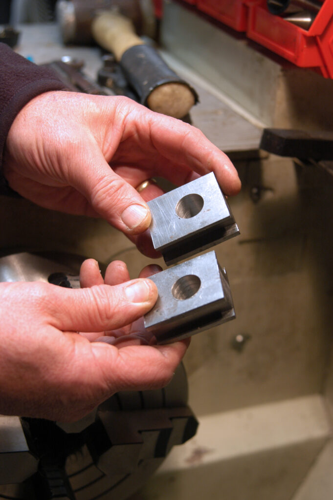
Next were the metal pieces that slide up and down in the centre cut-out of each side and hold the middle roller. Initially I milled a parallel guide slot on both sides of the metal holders, machining the total depth fractionally greater than the width of the frame cut-out slot to allow for slight play.
Curve
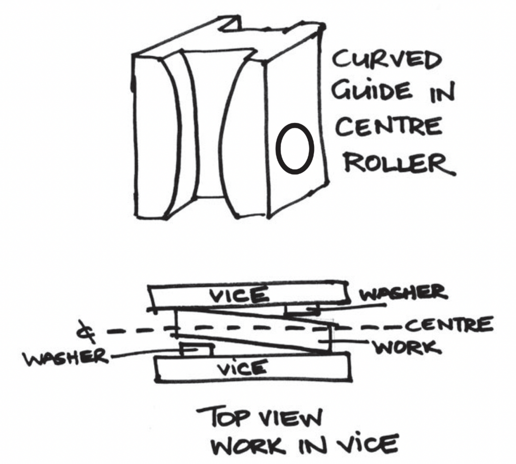
Then, to allow the centre roller not only to wind up and down but to stop it jamming if one side was wound more than the other, I machined a curve into the side walls. To do this, I inserted a packer washer in the front left-hand side and the rear right-hand side. This allows you to mill an angle in one half of each side. (See drawing.) Once you have done this, swap the washer to the other sides and repeat. Finish by hand-filing a curve into the slots.
I then machined the third top roller and put the bottom roller back in the lathe to machine out a groove to allow me to roll round bar (6 mm in my case). I also partially reduced the length, on one end of all three rollers ,to create a small space if I wish to roll a thin metal piece that has a folded lip. A friend with a broach cut out a keyway in the sprockets and I milled a corresponding slot in my roller axles.
If you haven’t access to a broach, then you have a couple of options. You could drill down through the sprocket and shaft on the end so that the hole is half in the sprocket and half in the roller shaft. Put a thread in and then a grub screw. Or you could drill through them both on the top and fix them with a roll pin or nut and bolt.
Roller holes
In the side frames, I drilled the holes to take the rollers. I reamed them to suit the finished roller-shaft size so that the rollers fitted in freely but with very little play. I have not bushed them at this point and will see how this works. If I find in the future that the holes are wearing, it will be easy to enlarge the holes and insert a bronze or hardened steel bush.
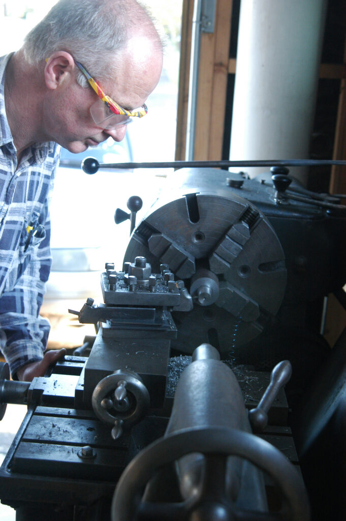
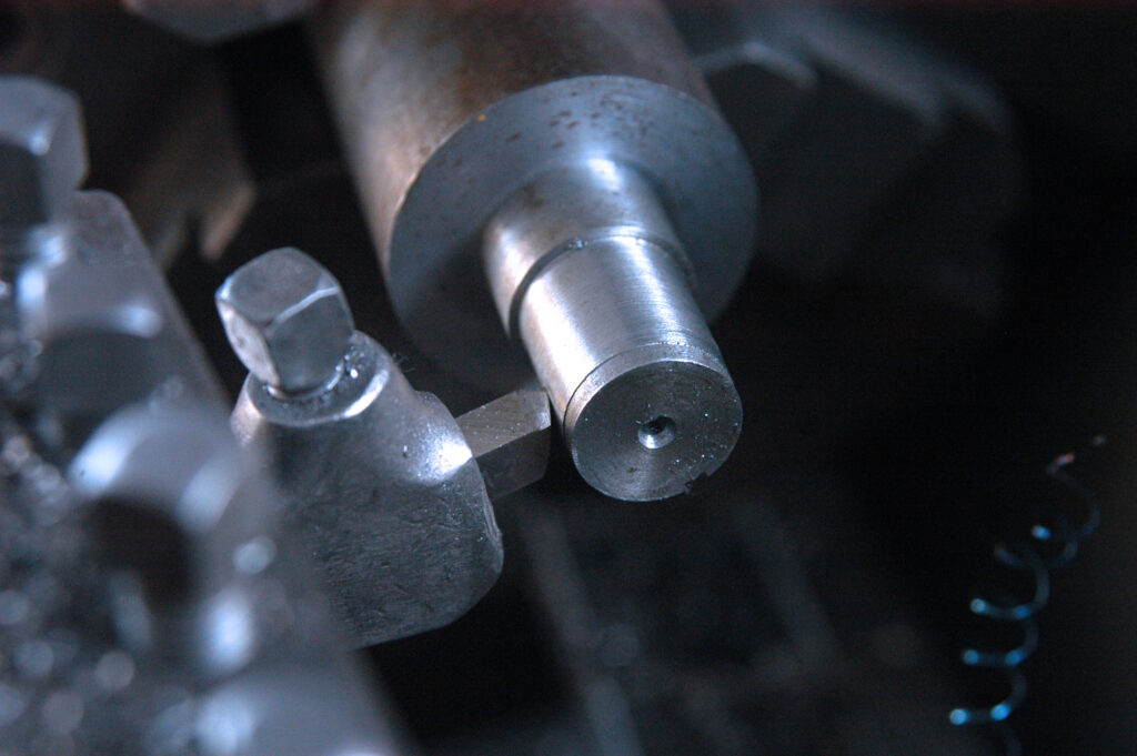
For the hole for the third adjustable roller, I marked the position in the centre of the metal sliders and at least three-quarters of the way down. It means the sliders don’t come into contact with the bottom rollers. I clamped the two metal slide pieces together to ensure parallel holes and placed them in a four-jaw chuck on the lathe to machine them out. I worked my measurements from the inside machined surface not the outside. This is in case you haven’t machined the groove evenly on both sides.
At this stage, drill a hole in the top centre of the metal sliders for the threaded rod lifter. Then drill and tap a small hole about 5 mm down from the top on one side. A small bolt in this hole will fit into a groove machined into the threaded rod lifter.
Brackets
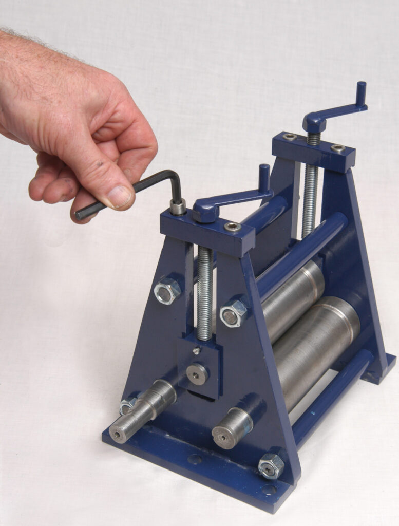
Time to make the top retaining brackets from 16 mm square steel. I milled a slot to match the thickness of the frames to assist with locating them. Drill the four holes for the cap screws so that they screw in flush with the top.
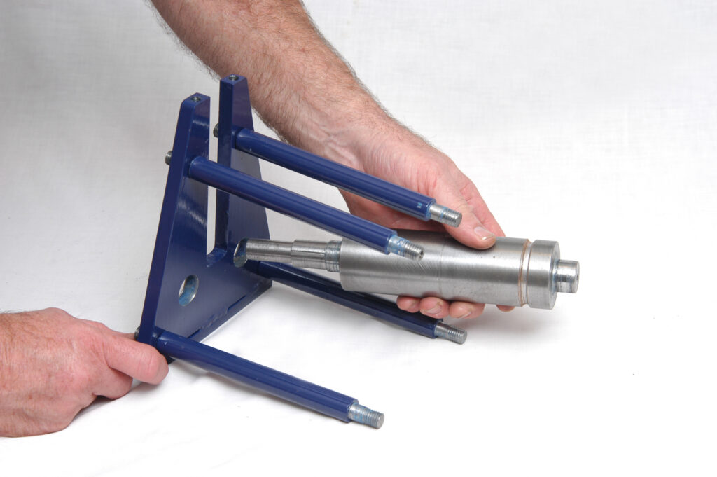
Next was to machine the spacer brackets which hold the frame walls apart. They are all done to the same length and with a thread cut into both ends. Make the spacer a good fit into the frame hole for stability.
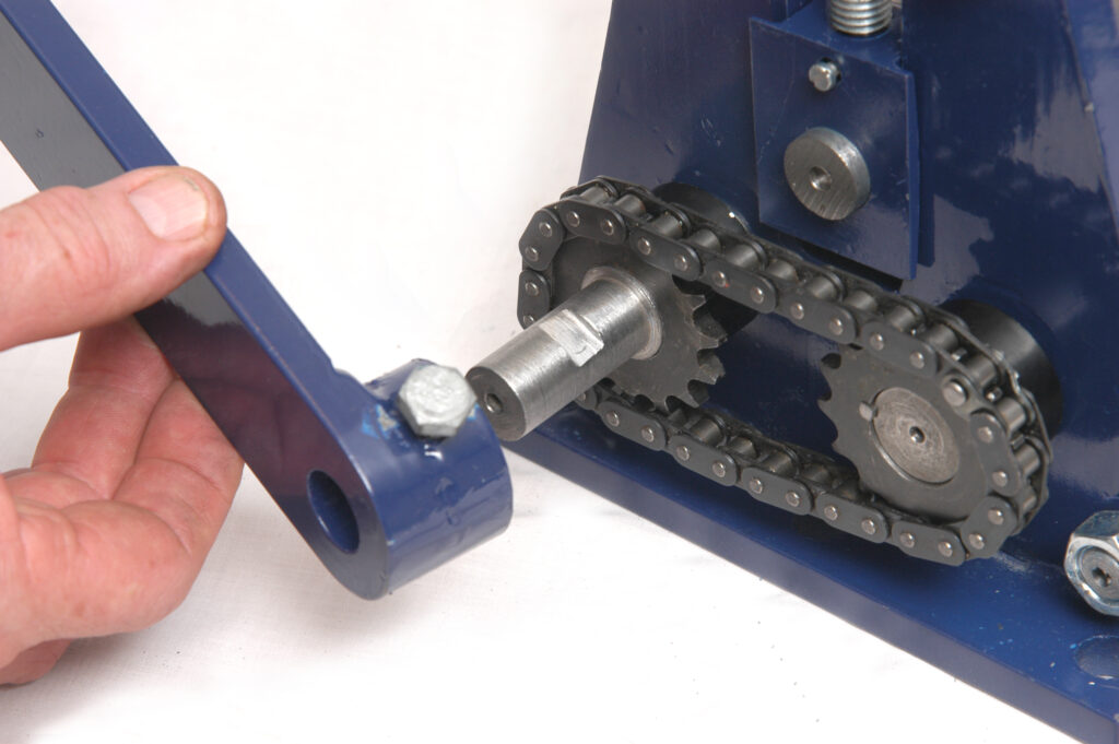
For the handle, I have guessed the length required and made it longer than maybe it should be. I intend to experiment with different handle lengths. I machined a bush down, welded it to the steel and then drilled the hole for the shaft. This is to ensure that it all lines up perfectly. My handle is a piece of pipe and a length of thread rod with a nyloc nut so it is free to turn
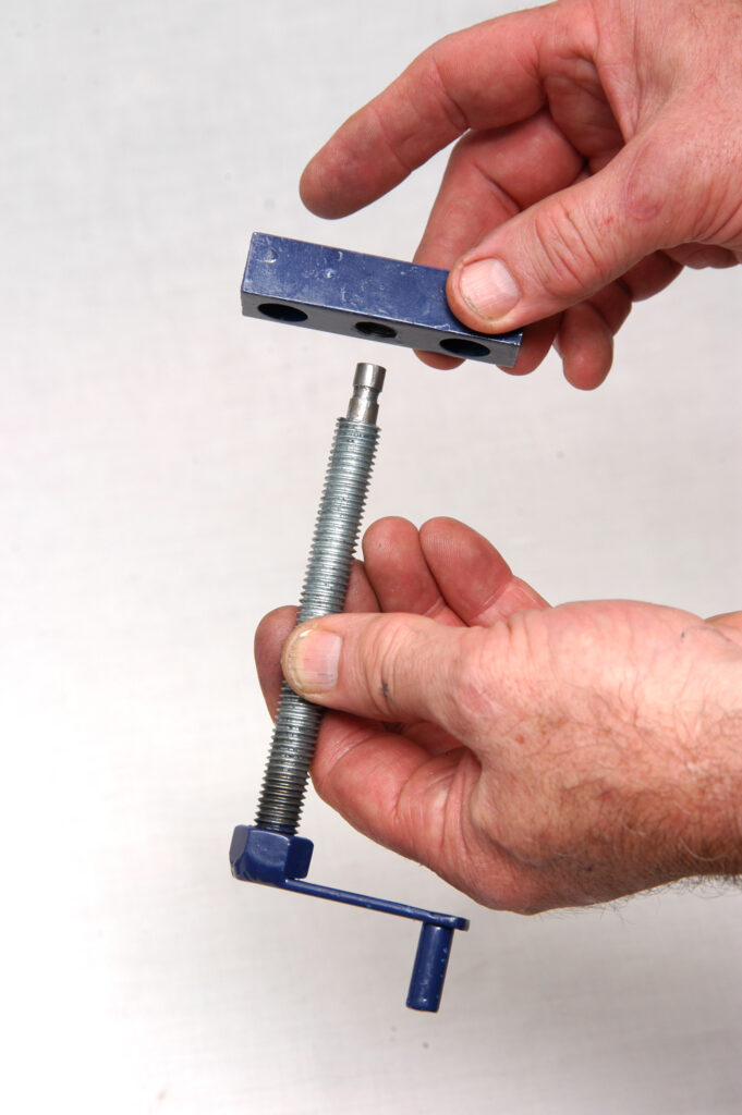
I did the same with the two screw handles on the top of the threaded rod lifters— just a nut welded onto a bit of steel with a small bit of rod at the other end. The nut was drilled and pinned to the threaded rod.
On the other end of each rod, to make a small groove I machined the thread, down at to the diameter of the hole where it fits already drilled in the slider. The small bolt that fits in this groove through the corresponding threaded hole in the adjustable metal sliders ensures that, when you wind up the roller, the sliders come up.
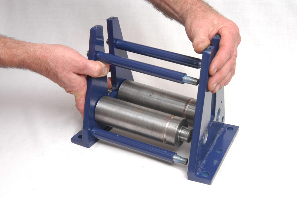
Now is the time to do an initial assembly. Firstly, check that all fits and rolls freely. Secondly, fit the top brackets so that you can locate where to drill the threaded holes into the frames for the top brackets. With the threaded rod in position, you can measure to both sides of the frames to centre. If after all your careful aligning you find that it’s not lifting as smoothly as planned, you may need to put on a shim under the retaining brackets at the top to make a slight adjustment to the alignment.
Once all is working as planned it’s just a case of pulling apart and painting. Don’t forget to block the shaft holes—I did and so had to spend some time sanding out the paint for the rollers to fit back in.
Now all that’s left to do is assemble and get on with the original project.
