A classic car gets variable-speed wipers run by Arduino
By Mark Beckett
Photographs: Mark Beckett

I own an American classic car and there are a few mod cons that are missing. I’ve added central locking because crawling over seats was a pain, but I thought the Arduino could add a few features that aren’t available in the shops. This is the first of two parts which uses the same piece of Arduino hardware to do two different tasks—run variable-speed wipers and a temperature gauge. Each can be used on their own as it makes no difference to the software.
Variable wipers
Most modern cars have a mode that allows the wipers to wipe at a selectable interval. I seem to find the time between wipes is either too fast, or too slow, resulting in the need to change the setting or turning it off and then on. It would be much better if it was infinitely variable. The basis for this project lies in a circuit I built many years ago, but never installed. It used a number of discrete integrated circuits (ICs) and a bunch of other components. This version uses an Arduino Controller and a few other low-cost parts.
Windscreen wiping
The system works because you can control how frequently the windscreen wiper goes across the windscreen. It starts to drizzle and rain hits the car window. You press the Start button and the controller signals the wiper to sweep once and stop. One wipe can sometimes be enough. The controller has operated a relay for 1.5 seconds, started the wipers and parked the blades to complete the cycle.
But the controller remains active and waiting for up to 30 seconds before a timeout instruction kicks in. If more rain hits the windscreen, and you press Start before the 30 seconds is up, the wiper moves again, but now keeps wiping the windscreen at the interval of seconds between the first Start push and the second Start push, say ten seconds. It keeps going at this interval until the Stop button is pushed.
If the rain now gets heavier, as our rain can, another press of the Start button during this ten-second cycle sends an instruction for a more frequent wipe which will happen at the interval between the last wipe and the most recent push of Start. It could be now every five seconds or even faster if you press Start more. The more you press the Start button the shorter the interval at which the wiper sweeps across the glass.
In other words it is infinitely adjustable, to suit changing conditions. When the rain stops or slows down, a press on the Stop pushbutton will stop the wipe interval.
Software (sketch)
The Arduino is more than capable of running very large sketches or doing multiple things at once. The trick is to make sure nothing slows it down.
This sketch has been written to allow a second function to run at the same time. Some of the inputs are used in the second function, but the software decides when and what to use, just as other pieces of technology use some of the buttons for other things.
To make sure we don’t slow down the Arduino, we remove any delay (X milliseconds) commands and use the internal timer. We note the time and then check to see if the “current time minus the noted time” exceeds any of our “delays,” and we either do the task, or go back and do something else.
A simple way to compare this would be if you were filling a swimming pool. You could stand and wait for it to fill or you could go away and do something else and come back every ten minutes to check on it. As you went about your other tasks (having a cold one), you would look at the time and see if it’s ten minutes since the last time you checked and act accordingly.
To download the sketche for this project see https://the-shed.nz/arduino-software/

Connections
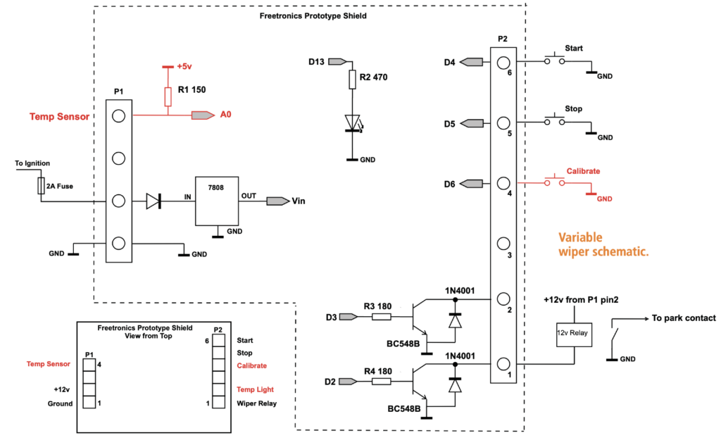
The connections required are 12v power, ground, Start button, Stop button and the output to the relay. The connections are made on the shield (plug in board) via a screw connector for ease of installation. There are some other parts shown in the construction photos, that will be used for part 2. These can either be fitted now, later or not at all.
Regulator
The Arduino boards suggest they can handle 12v. However, they use a low-voltage regulator so voltages above 12v can be a strain. A vehicle charging system is usually 14.2 volts. It can fluctuate, and I wanted to make sure that any alternator or regulator fault didn’t result in a fried Arduino.
The 12v power is fed to an 8v regulator and some filtering capacitors to ensure the voltage doesn’t exceed the regulator on the controller. This approach also helps to remove any electrical spikes that can be present in any automobile electrical system.
Push buttons
The Start and Stop buttons are simple push buttons (momentary) and have to work just with 5v and with no current. I haven’t finalised the buttons I want so these will do in the meantime and are hidden from view.
Normally a switch will put 12v power onto the lights, etc, but there are circumstances where we have power on the device and switch the ground to complete the circuit.
An example is the interior light. Here, one side of the lamp is connected to 12v and the other side connects to the door switches. When the door is opened, the switch completes the circuit and the interior light operates.
We do the same with the Start and Stop push buttons. We wire them between the inputs (D4, D5) and ground. When the button is not pressed, the input pin is held HIGH (+5volts) by the internal “pull-up” resistor. It goes LOW when the button is pressed.
The internal pull-up resistors are built into the controller chip. These are 20k ohms (20,000 ohms) and are configured when the pin is designated as INPUT, and you set it HIGH.
pinMode (StartButton, INPUT);
digitalWrite (StartButton, HIGH);
Debounce
All switches have a “bounce” period before they settle down to a steady state. While this process is going on, any fast software will think you’ve pressed it many times.
In a quick check of the software, it would have detected the pushbutton 71,000 times in one second, so you can see how important it is to put some limits in place within the software.
My sketch (software) checks the buttons every 5mS, but includes a counter to ensure it has been pressed for 50mS before doing what is required.
After that, we ignore the start button until after the relay ON time (1.5 secs) has expired, as it can’t wipe again until then and you’re not likely to hold the button on for more than one second.
Wiper relay
The controller output is not powerful enough to operate the wiper motor, so we use a relay contact.
The output (D2) uses a resistor and transistor with a diode across it to switch a 12v relay.
The diode prevents the back emf (electromotive force, the energy released when the power is removed from the relay) from damaging the transistor or upsetting the electronics.
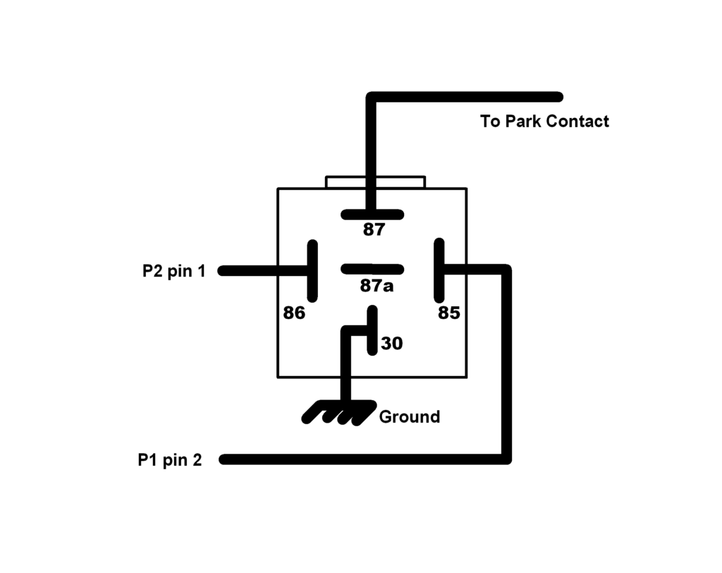
When you switch your wipers off, the park contact in the wiper provides a ground to the wiper motor (another example where the ground is switched) to bring them back to the “park” position.
We connect the relay contact across the wiper “park” contact and fool it into thinking it hasn’t parked yet. The controller operates the relay for 1.5 seconds, which starts the wipers moving and the wipers park contact will park them.
Controller choice
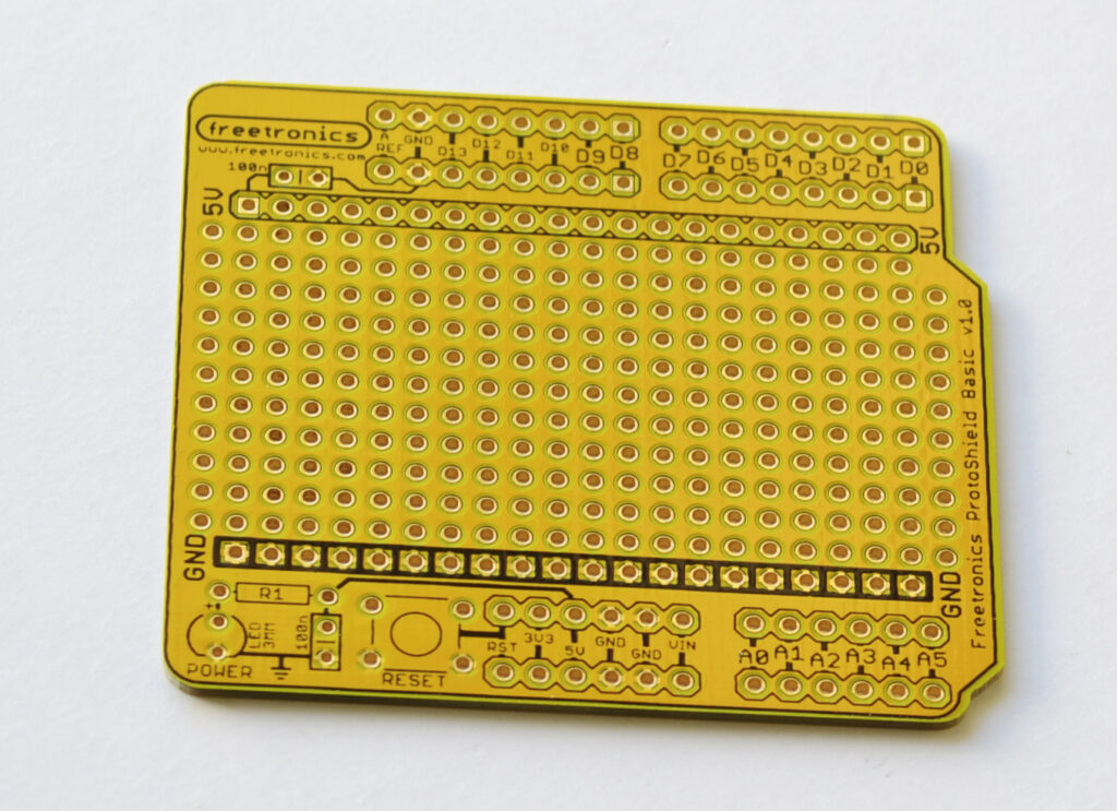
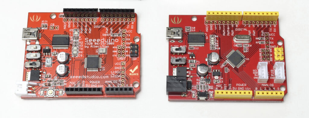
I chose to use a shield (add-on board) to house all the parts for this project that allows the use of any standard Arduino and settled on a Seeeduino V3.0 and a Freetronics prototype shield, as being an inexpensive solution.
Back emf
A relay relies on magnetic force to pull the armature in and operate a set of contacts. Once this magnetic force is started, it likes to keep going, so when we turn off what is causing it, it generates a voltage in the coil while it dies out. This voltage is opposite the original, and can be many times larger than the voltage used to operate the coil in the first place.
There is an excellent video here. http://scripts.mit.edu/~tsg/www/demo.php?letnum=H%2017
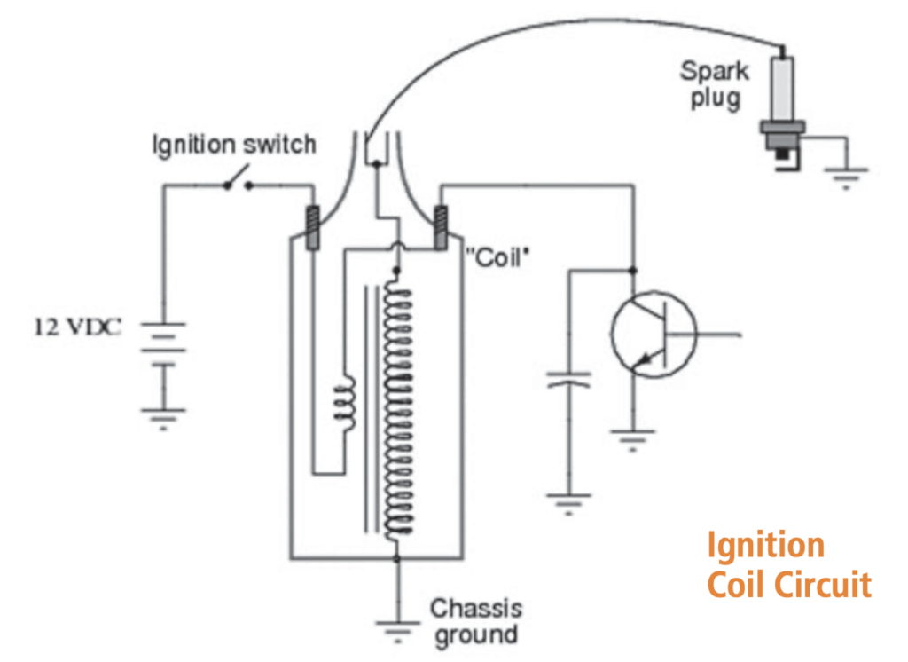
This induced voltage is vary handy for our ignition coil to generate the voltage across the spark plug but in the case of our poor little transistor, it’s likely to damage it unless we do something to protect it.
For our ignition coil example, the capacitor provides protection and makes the coil “ring” or oscillate to produce a longer spark time just as it would if there were points used.
To stop our relay destroying transistors or creating other undesirable voltages, the simple method is to place a diode across the coil (or the transistor). The diode is reverse-biased so that it conducts only if the battery was reversed. This method can increase the release time of the relay by 2-5 times, (as I discovered) but in our case this is not important and will not damage the contacts.
Some good links for relays and pictures of the internal workings in plain English can be found at
http://www.bcae1.com/relays.htm and you can search for other helpful internet sites.
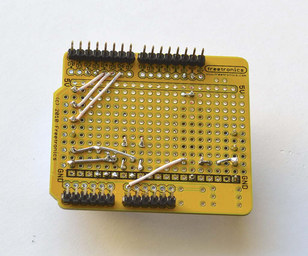
Construction
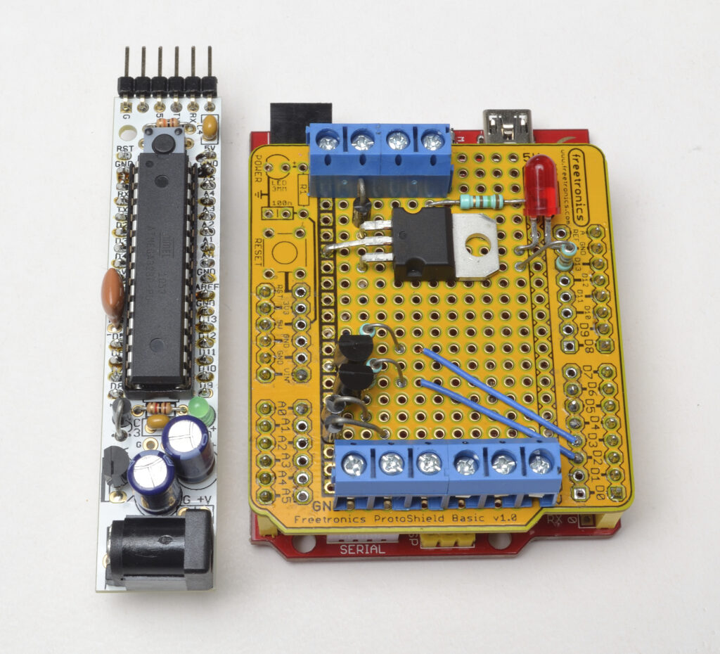
Each of the holes on the prototype shield is insulated from each other so we bend the component leads and solder them together to make the connections. For the interconnecting wires, I stripped some salvaged Cat 5 cable but any insulated wire will do. Refer to the schematic drawing and photos to help you.
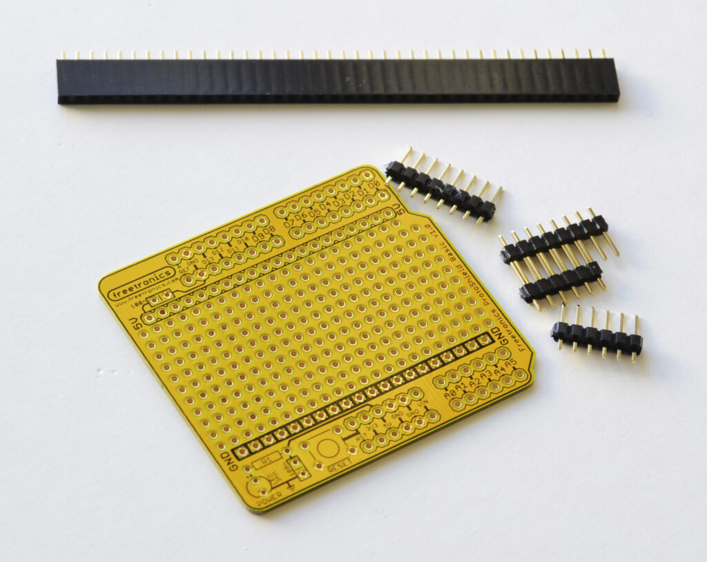
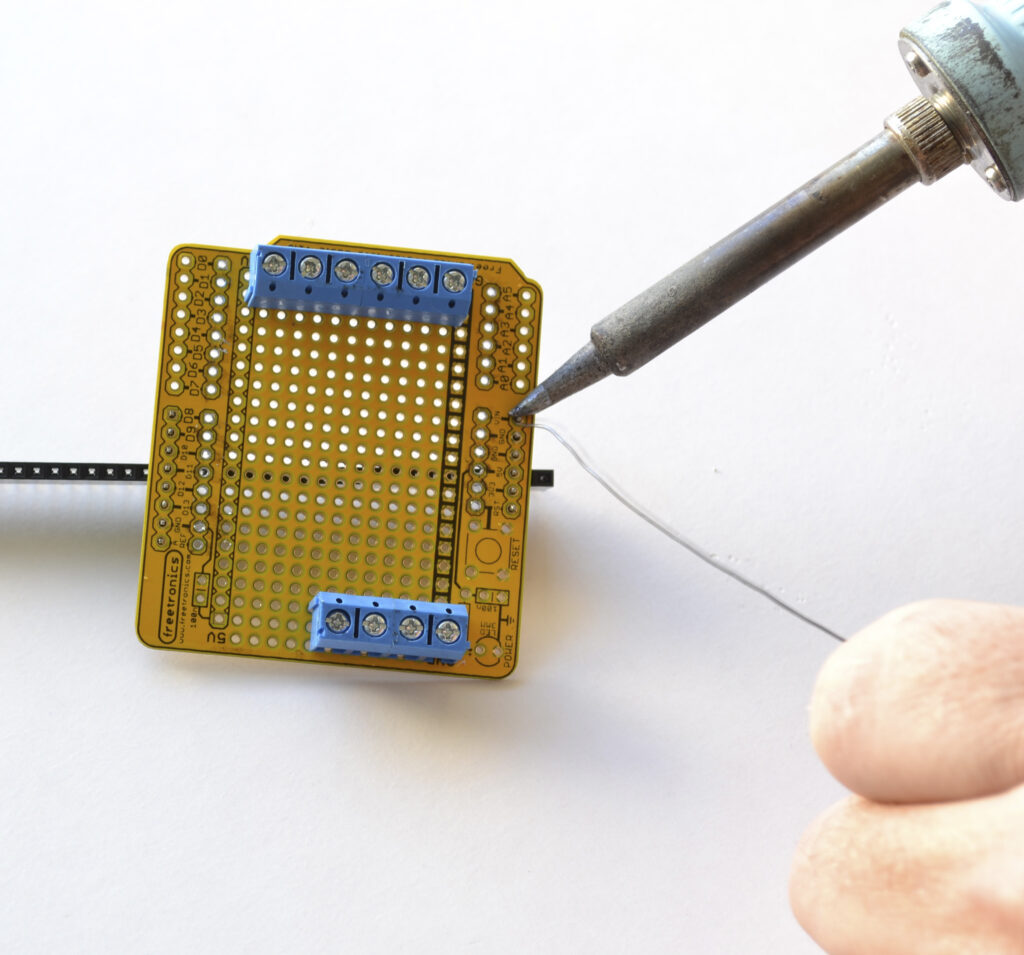
The screw terminal connectors are the first thing to fit and luckily Hadley has these available. At all the normal stores, it was frustrating to find only those with pins too big.
I chose a pair of two-way and a pair of three-way which have small dovetails moulded into the body to allow them to be joined together. You’ll need to join them before inserting them into the board and soldering.
The header pins are next. Cut them to suit and place them in the outer holes of the shield.
I used a piece of header strip to hold them before soldering one end pin, checking they were straight and flush with the board, before soldering the other pins.
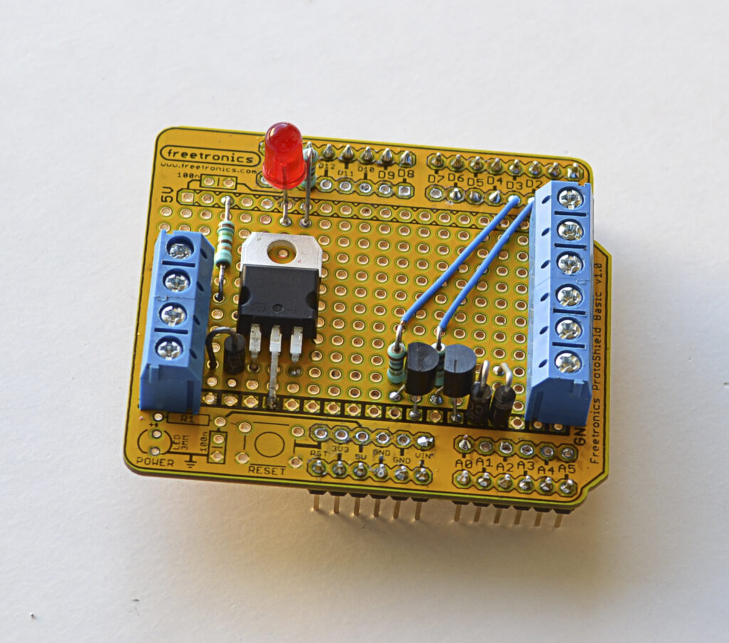
The diode is bent carefully using pliers and stands up with the line end (anode) facing the 8v regulator.
The pins on the regulator are arranged so the middle one (ground) connects with the ground strip and the body sits against the board. (After we’ve tested it, we’ll add some support to stop it vibrating).
The transistor leads are arranged to allow the emitter to connect to the ground strip while allowing for the base resistor to be connected. As this board suits two projects, the second transistor is an option.
Add the back emf diode across the transistor, with the stripe connected to the collector, and the other end to the ground strip (See Panel:Back emf).
I choose to wire the collector of the transistors to the output connector (P2) before adding the base resistors. A wire on the topside connects D2 and D3 to the other side of the base resistors. D4, D5 and D6 have a wire running from them to the P2 connector pins, and this is on the underside of the shield.
The LED is used to show the sketch is running, I used a 470 ohm resistor from D13 and then joined it to the anode of the LED with the cathode connected to the ground pin next to D13. Once fitted in the case, the LED cannot be seen and is not necessary for correct operation. You may want to use a 3mm LED or mount it on its side if you use the case suggested.
WARNING: There are some tutorials that suggest a LED can be driven straight from the Arduino output pin which delivers 20mA. This is NOT a good practice, and a series resistor (330 or 470 ohms) should be added to limit the LED current to around 10mA. I can’t see the difference in brightness between 10 and 20mA of current. So unless you’re doing something special with high current LEDs add the resistor and save the grief.
Be nice…
Be nice to your controller. The Arduino chip (Atmel 328) has internal current limiting of 40mA on the output pins with a maximum of certain combinations of pins of 150mA total. If you do the maths 150 / 40 = 3.75, so if you don’t limit the output current, you will soon start experiencing strange results and sketches that won’t run properly. Many other controllers and electronic devices don’t have any limits and when the smoke comes out, it doesn’t work any more. So be nice to your controller and put a resistor in series with the outputs to limit the current.
Testing
It’s always a good idea to test a project like a controller for windscreen wipers before you fit it (I don’t care what the whiz kid said). In my experience, if you test it when you can see what you’re doing without being upside-down under the car dashboard, it means there are fewer things to check if it doesn’t work in the car.
You’ll need a 12 to 15v DC supply which can be a modified—an old computer power supply, plug pack or a car battery—and some short pieces of wire. Adding a fuse in the power lead is always a good idea.
Do a final check against the photos to see if you’ve connected everything and not added extra shorts in the wrong place. Separate the shield and Arduino, as we’ll test the shield construction first. (refer to the schematic).
Add the –ve of the supply (ground), to P1 pin 1 and the +ve to P1 pin2.
Using a voltmeter, check that you have approx 8 volts at the Vin (voltage in) pin.
Connect one side of the relay between P2 pin1 and the 12v supply.
Using a piece of wire, make a connection between pin D2 and either Vin or 12v.
If everything is wired right, the relay should click whenever the wire is connected.
Try putting the wire onto D3 and nothing should happen.
If you’ve added the second transistor, shift the relay to P2 pin2, and connect the wire between D3 and Vin or 12v. The relay should click whenever the wire is connected.
Try putting the wire onto D2 and nothing should happen.
We can test the wiring to the controller for the pushbuttons by connecting the relay into P2 pin4.
Connect a wire between ground and D6, and the relay should click.
Repeat for the P2 pin5 and D5, and P2 pin6 and D4.
If the tests worked, and there was no smoke, fireworks or other surprises, then congratulations.
Either solder a piece of wire through the regulator mounting hole, or use some adhesive to hold it to the shield and stop it moving.
Programming
You’ll need the Arduino Integrated Development Environment (IDE) which was explained previously (“Introducing Arduino” Feb/Mar 2012). Connect the USB cable into the computer, and plug the other end into the controller. Install the driver as explained on the Arduino website (www.arduino.cc).
Start the Arduino software, and under the “Tools” tab, set the “Board” to “Arduino Duemilanove w/ ATmega328.”
Set “Serial Port” to point at the new comm port the driver installed.
You’ll need to download the sketch from the website and load it into the Arduino IDE.
Under the “File” tab, open the sketch. (It may want to create a matching directory.)
Under the “Sketch” tab, click Verify/Compile and after a few seconds it should report “Done compiling.” If you have everything right it should report the size.
Binary sketch size: 3186 bytes (of a 30720 byte maximum). Press the right-facing arrow icon (just below the Edit), and it will compile (again) and upload to the controller.
The status bar changes from “Done compiling” to “Uploading to board” and the arrow icon changes back to normal when its finished.
If you get strange messages, check that you have set the right board and comm port.
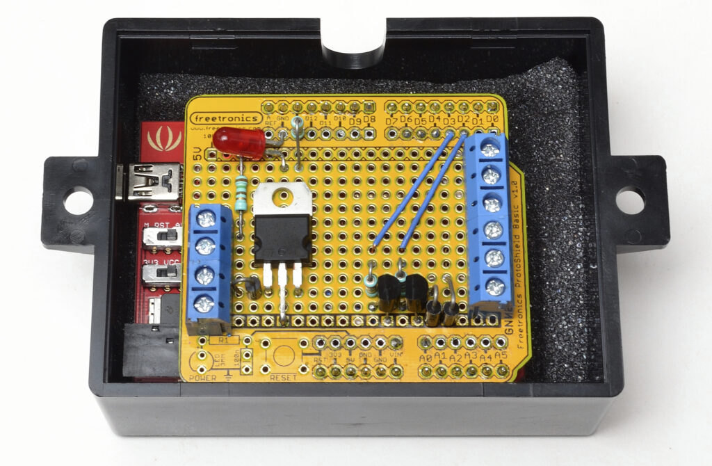
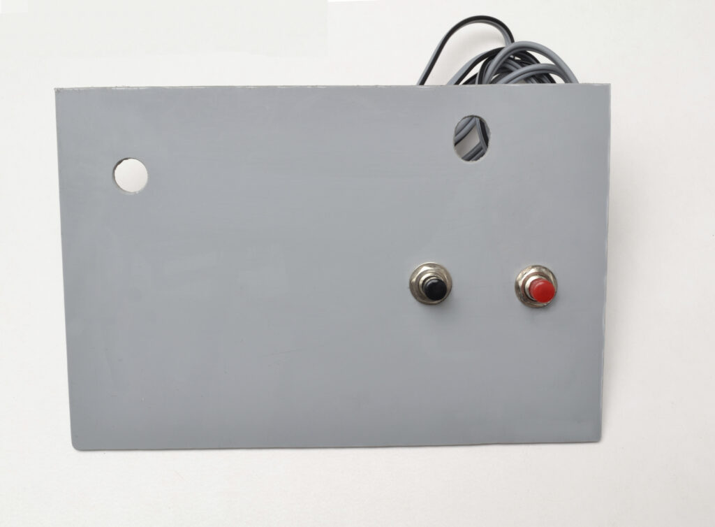
Case
I elected to use a Bulkhead case that could be screwed or tied to something behind the dashboard. Be aware that most case dimensions are outside and there’s just depth in this for the controller and shield. To stop the whole thing rattling around, I used the foam packaging that comes with the controller, and placed it underneath the controller. The wires are carefully routed around and out the in-built cable entry hole.
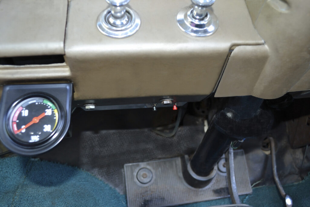
Installation
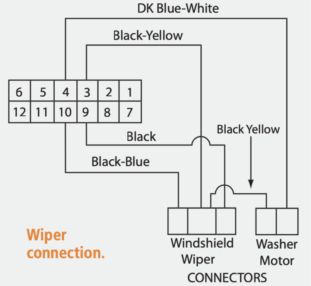
The first thing to do is indentify how the wiper is connected and what makes it run.
In my car, (as with most GM cars) when the ignition or accessories are turned on they provide 12v to the motor. The wiper switch then grounds one or more wires to complete the circuit. I searched the internet and found a wiring diagram and for the purpose of this article, the non-essential bits have been removed.
I proved the black wire on Pin 9 of the firewall plug had 12v when the ignition was ON and the wiper was OFF and that it went to zero volts when the wiper was on low speed.
The relay contact then goes between this wire (black in my case) and ground. Your vehicle may be different, so check first.
Sometimes the body of the switch provides the ground and won’t work if the switch is removed. If you blow the wiper fuse, chances are that something is NOT right, so check again.
I ran 12v from ignition through a 2 Amp fuse to P1 pin2 on the shield. The relay coil pin (86) also connects to this connector, so twist the wires together before inserting into the connector.
The other relay coil pin (85) joins to P2 pin 1, and the pushbuttons to P2 pins 5 and 6.
A ground wire runs from the body of the vehicle to P1 pin 1 and to the push buttons.
A second ground wire connects to pin (30) on the relay.
I tested mine on the floor, before going upside-down to fit it under the dashboard.
I intend to change the pushbuttons in the future and for the meantime I fitted them so they were under the edge of the dashboard, and out of sight.
I hope this project has sparked some interest in using Arduino to do what was previously a difficult task.

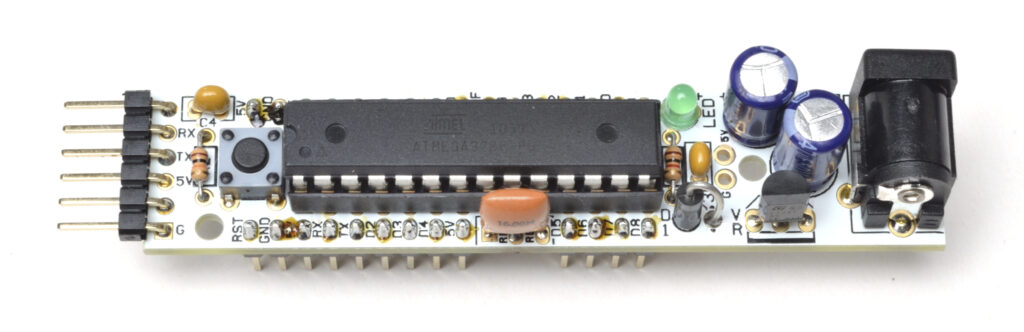
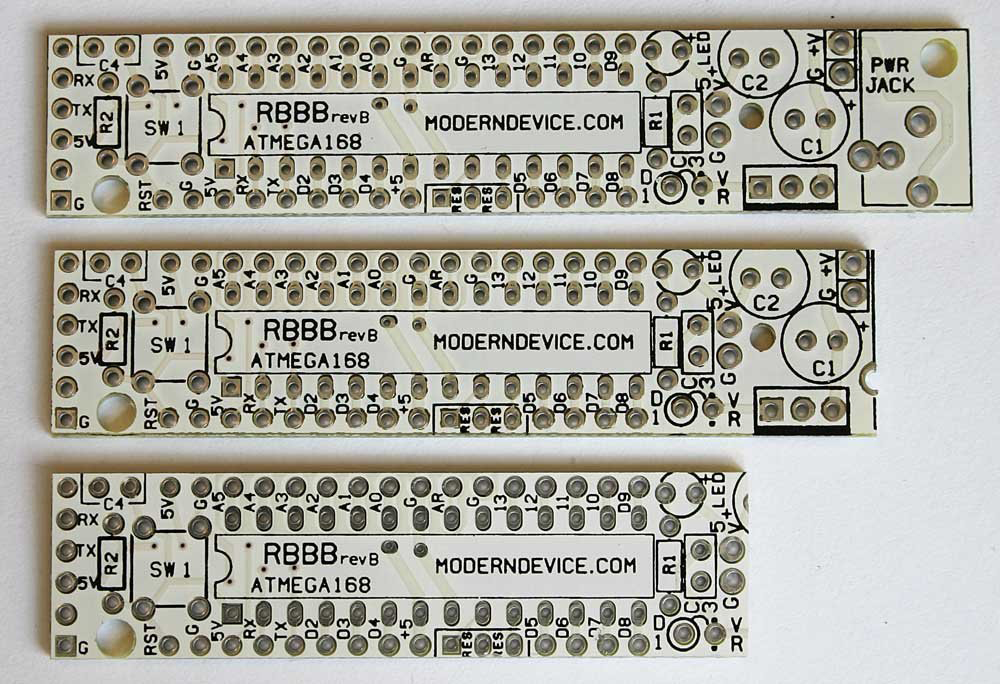
Alternative construction
I imported a RBBB (Really Bare Bones Board) kit for another project, but it struck me that if I replaced the regulator with a 7805, I could apply the 14+ volts present in a vehicle and not worry about it. These have been designed so that various parts of the power end can be removed to suit your application. I also found some DC Solid State Relays (SSR) in New Zealand at a very reasonable price. Using one of these, you don’t need to have the transistor and diode. With the 8v regulator gone as well, this means that the need for a shield has gone as well. Despite the label stating 24-220V DC, it works well as low as 6V DC.
Programming is by a USB to serial adapter, or simply plug the chip into your UNO or Duemilanove, program it and then pop it back into the RBBB.
Internal timer
One of the great things built into the Arduino is an internal timer. It can be read with the command millis() and counts the number of milliseconds since the program started. It is what is known as a “unsigned long” number (from 0 to 4,294,967,295, which is 49 days, 17 hours, 2 mins, and 47.295 secs.).
So any variables that you will use to store this should be declared as “unsigned long,” that is unsigned long LastButtonCheck = 0; // Time the Buttons were last checked.
In the sketch (program code) for the variable wiper at Line 140 (void Check_Buttons() ) we use the timer.
We have previously noted the time when we checked the buttons ( LastButtonCheck = millis(); ) and next time through we check to see if the current time has increased by 5mS (or more).
if (millis() – LastButtonCheck > 5)
The advice from the forum is to always to subtract the numbers ( millis() – LastButtonCheck ) before comparing it. In this case is it greater than 5 ( >5).
There is an example (2. Digital – Blink Without Delay) within the Arduino integrated development environment (IDE) which shows how things can be slowed down by replacing the delay() function, and using the timer.
(timer.http://arduino.cc/en/tutorial/BlinkWithoutDelay)
I have used the same principle in this sketch.