Guarantee precision with the simple trick of sighting a dot where you want to make a punch mark.
By Ian McIntyre
Photographs Gerald Shacklock
Diagrams Ian McIntyre
Over the years I have tried many new ideas and products, some useful, others quite useless.
As I ponder this, I think of the inventors of the one-piece jigsaw puzzle, the pedal wheelchair, and the L-shaped caravan. For some reason there was something impractical about all these ideas – can’t think what. But this optical punch is useful, and for me in recent times, as I now wear glasses to see, quite essential.
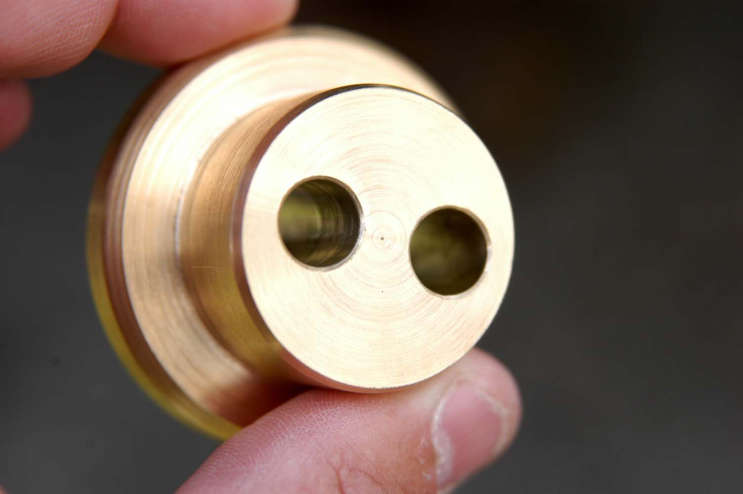
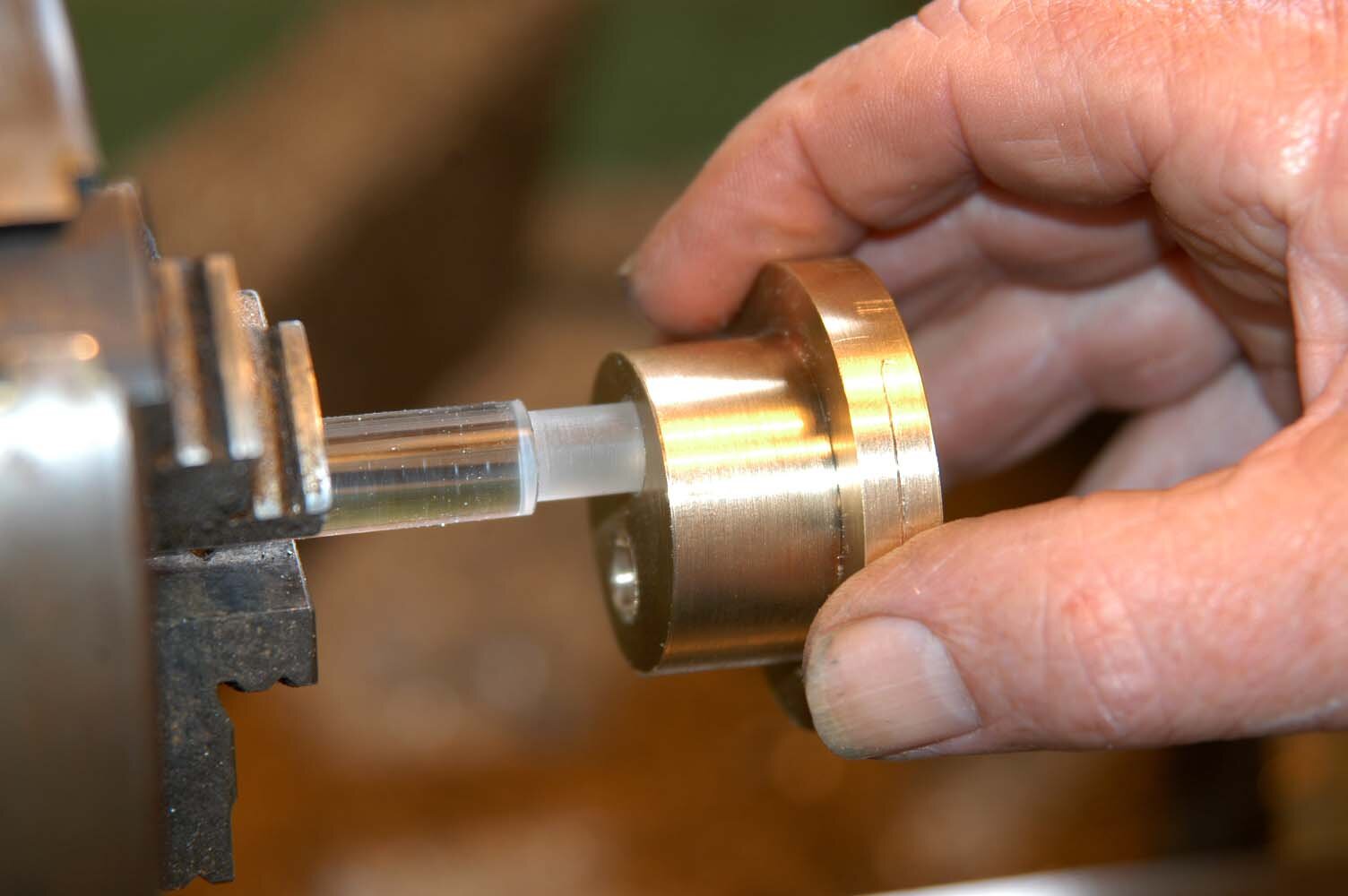
An optical punch consists of a brass body with two holes through it, one for use, the other for storage, because there are two rods. One rod is the punch, the other a vertical magnifying glass made of a plastic rod. You look down the viewing rod at a dot marked on its base. You then move the whole apparatus around until you can see the point where you want to put a punch mark. Holding the brass body, you remove the plastic rod and drop the steel punch back into the same hole, then hit it. Result: a perfect, vertically punched mark, precisely on the spot.
This project is not a new idea, but one that I found many years ago overseas. It has let me do things more accurately and removed that sick feeling when things turn to custard because of inaccuracy in drilling holes in metal. Every time you are out half a millimetre at the centre, you are a long way out at the outside. If the punch mark has an uneven edge because the punch was not vertical, the drill will push away from the high side, making the inaccuracy even worse.
Apart from the difficulty of seeing where to put a punch mark, especially if you have rolled the punch over onto the spot, one normally gets some parallax error in centre-punching. The optical centre punch will cure that. It can be made using a metal turning lathe and a drilling machine, and a means of hardening the punch such as gas or a blowlamp.
Raw material
I made the body from 50.8mm (2”) diameter brass but it could be aluminium (steel can rust without treatment). The centre punch is made from a 10mm diameter rod of common tool steel called “silver steel” and the optical viewing rod is from a 12.5mm (1/2”) diameter bubble-free clear acrylic rod. Because this American rod is in imperial measurement, the metric size when it’s bought may vary down to about 12.1mm. The measurement is given as 12mm in this project for safety sake, but the top part of the viewing rod is essentially to be left as purchased.
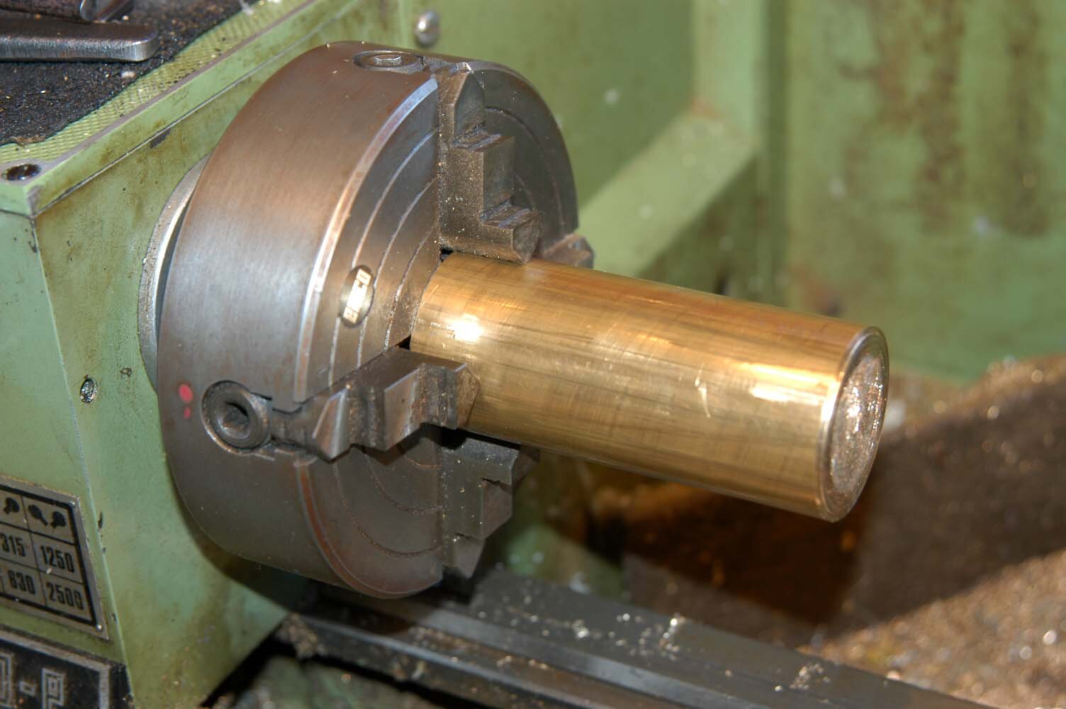
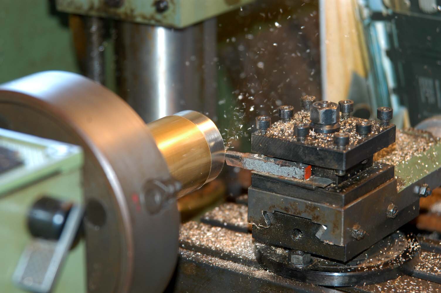
Lathe machining
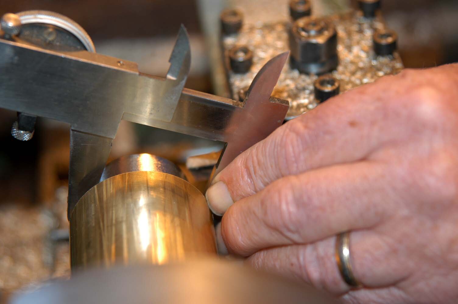
Mount a 4-jaw chuck and load the 50.8mm brass rod into it. Don a safety helmet and with a very sharp roughing cutting tool, face off the rod. Next turn the body to size (35mm diameter to an 18mm depth, with an 8mm base deep base at the 50.8mm diameter). Take care to ensure that the depth of the brass body for each turned diameter is within 1mm of the correct measurement. This is to ensure that the lengths of the centre punch and the optical rod will have the correct depth when inserted into the body. Change the cutting tool to a round-nosed tool and take a skim over the turned surfaces to give a smooth finish.
Parting off
Remove the turned part from the 4-jaw chuck, mount it in a vice and carefully cut the turned part off, making sure there is adequate length to square off the base in the lathe, say an extra 4mm. Remove the 4-jaw chuck from the lathe and fit a 3-jaw self-centring chuck.
Drilling
Base and recess
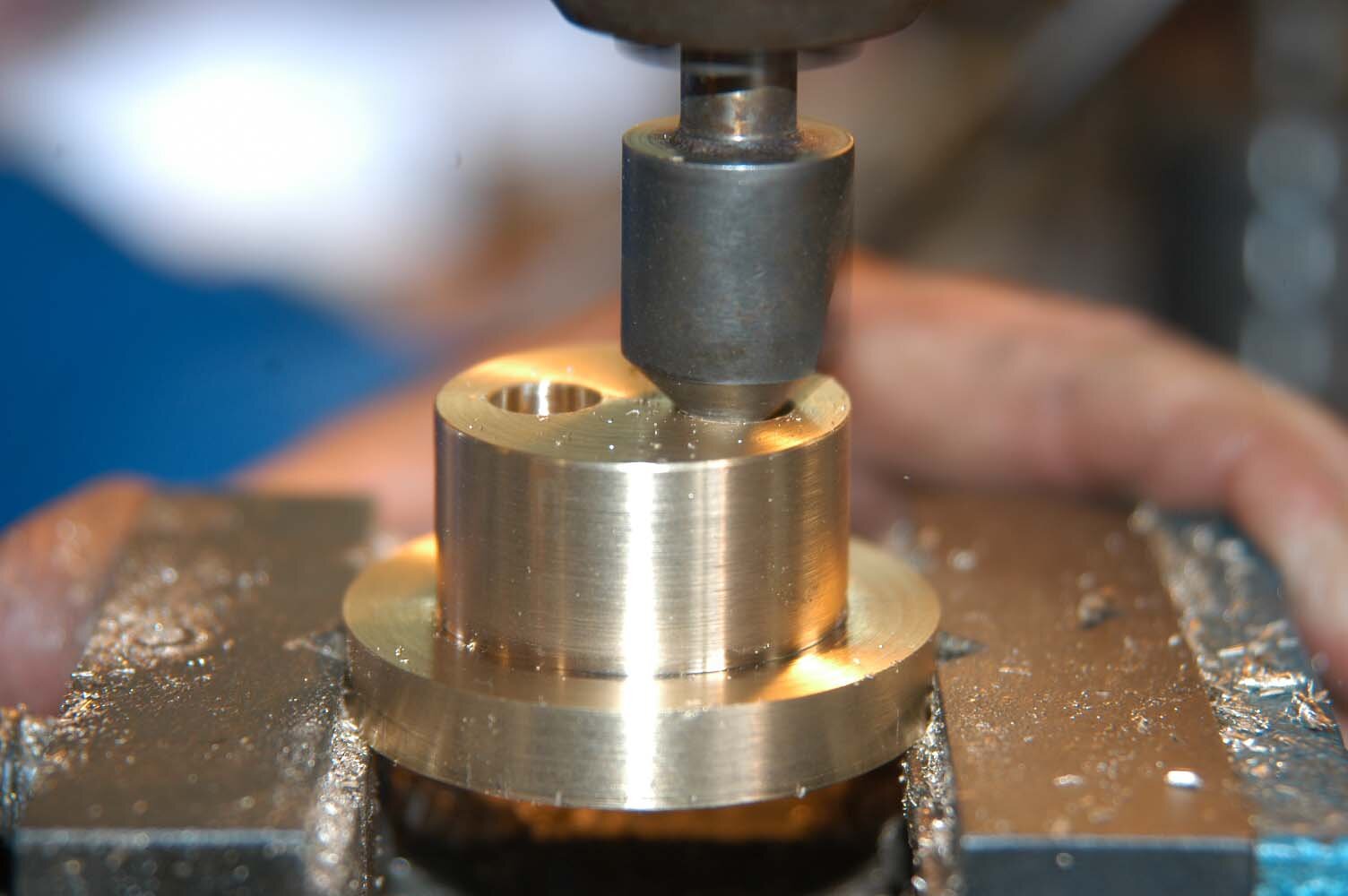
Fit the body into the chuck jaws using the 35mm section for gripping. Face off the large diameter to create an 8mm deep base for the body (first checking the total depth of the body to ensure it is within specifications shown on the drawing, 26mm deep in total). Turn the recess out to a diameter of 35mm at a depth of 2mm and remove the body from the lathe.
Hole centres
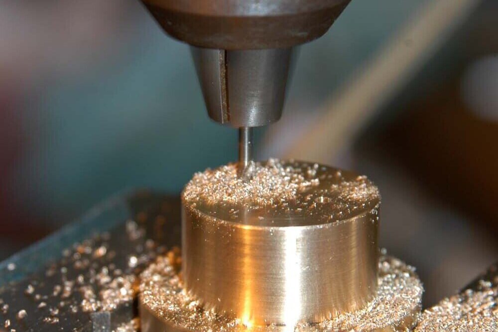
Using a centre square, scribe a line across the top of the 35mm diameter section and using Odd Legs or a measuring rule, mark the centre of each of the two holes to be drilled and centre-pop each of them.
Drilling
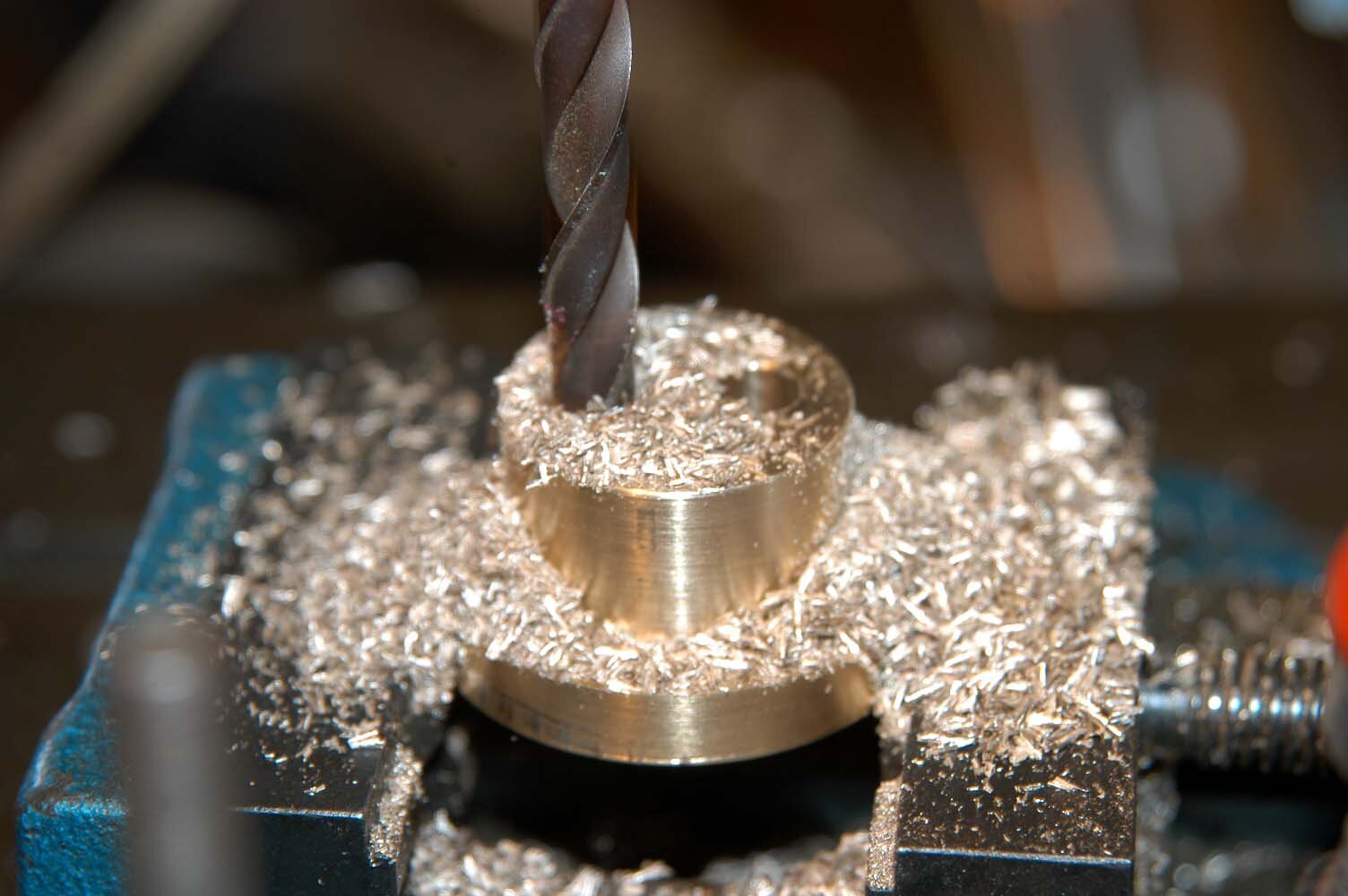
Mount the body in a drill vice and drill pilot holes of, say, 2.5mm for the two holes right through. As the diameter of these holes needs to be accurate, I used step-drilling, starting with a drill of 9.3mm diameter, then a 9.4mm diameter, then a 9.5mm diameter. I clamped the body in the drill vice, which was clamped to the drilling machine table. This way, I could change drills without shifting the drill vice. Ensure that the drill feed is very slow so that ridges are not built up in the inside of the holes.
Repeat the step-drilling process with the second hole. Debur each of these holes at both ends using a lathe deburring tool or a large drill of say 12mm “backed off” (cutting edge flattened with an oil stone). Finish the holes by wrapping a small piece of 200-grit Wet and Dry sandpaper around a 9mm drill shank and give the inside of the holes a bit of a shine.

Chamfer edges
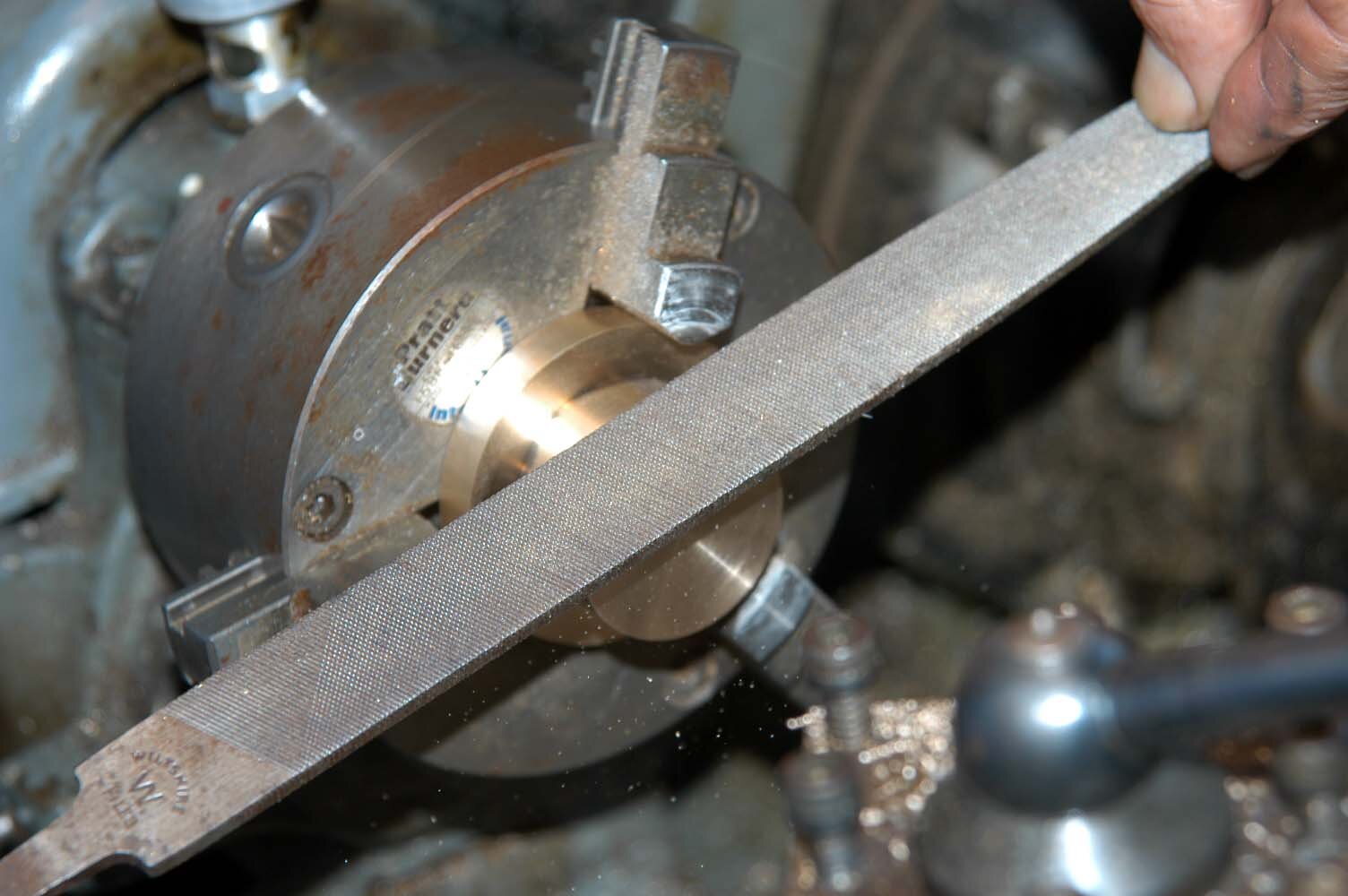
Mount the body back in the lathe, gripping the 35mm diameter section. Using a lathe tool and smooth file, chamfer the edges and face of the 50.8mm section. Reverse the body in the lathe chuck and repeat the chamfering for the other end of the body, using the file.
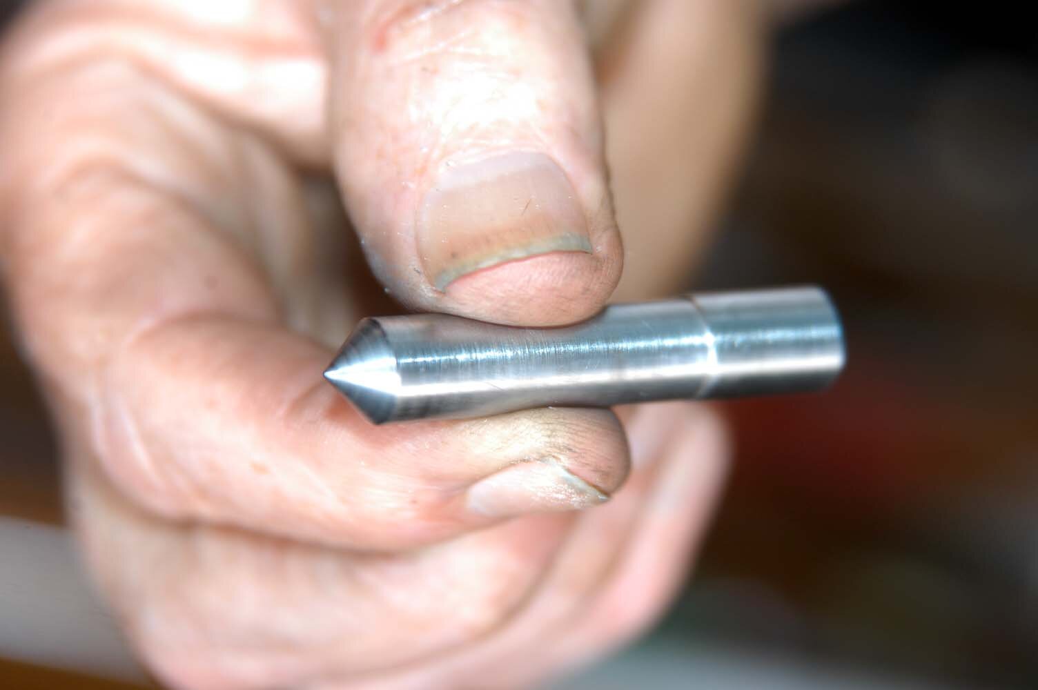
The punch
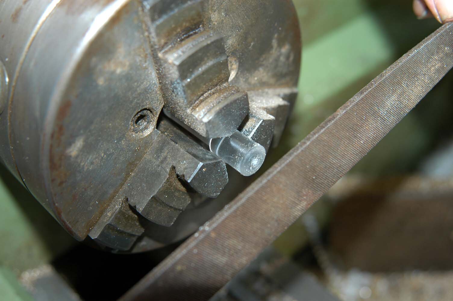
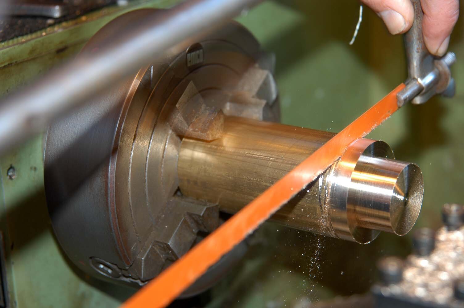
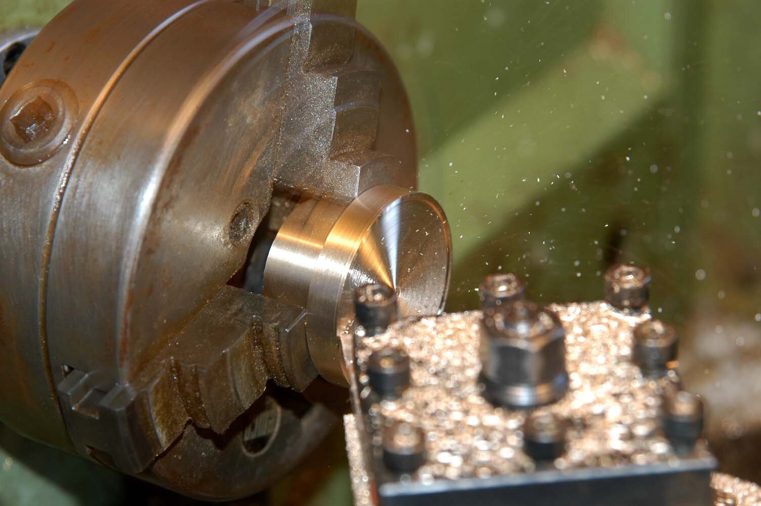
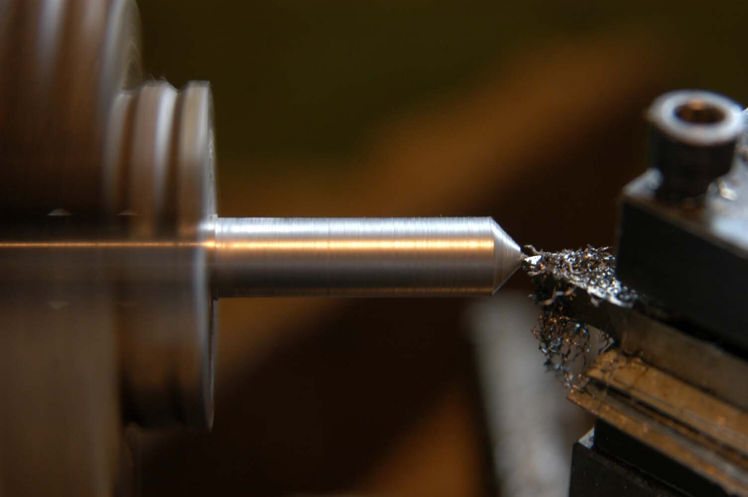
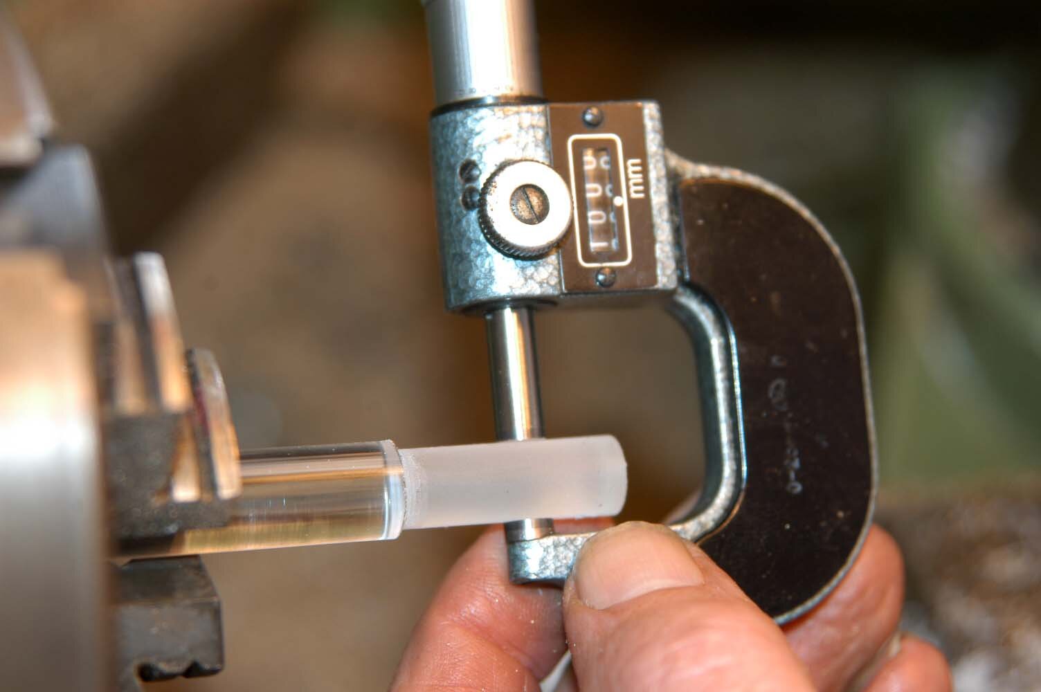
Cut a length of about 100mm from the silver steel rod and mount it in the 3-jaw chuck. Turn a 35mm section CAREFULLY to the exact 9.45mm diameter size. A neat sliding fit is required for the punch to go into the body holes so GREAT care must be taken. A good micrometer is required for this operation. Give the punch a pointed end using the lathe top slide set at an angle of 45 degrees to the lathe’s centre line, and then cut the punch to its 50mm length using a saw, or part off in the lathe. Reverse the punch in the lathe and face off the end, and then chamfer the edge with a smooth file.
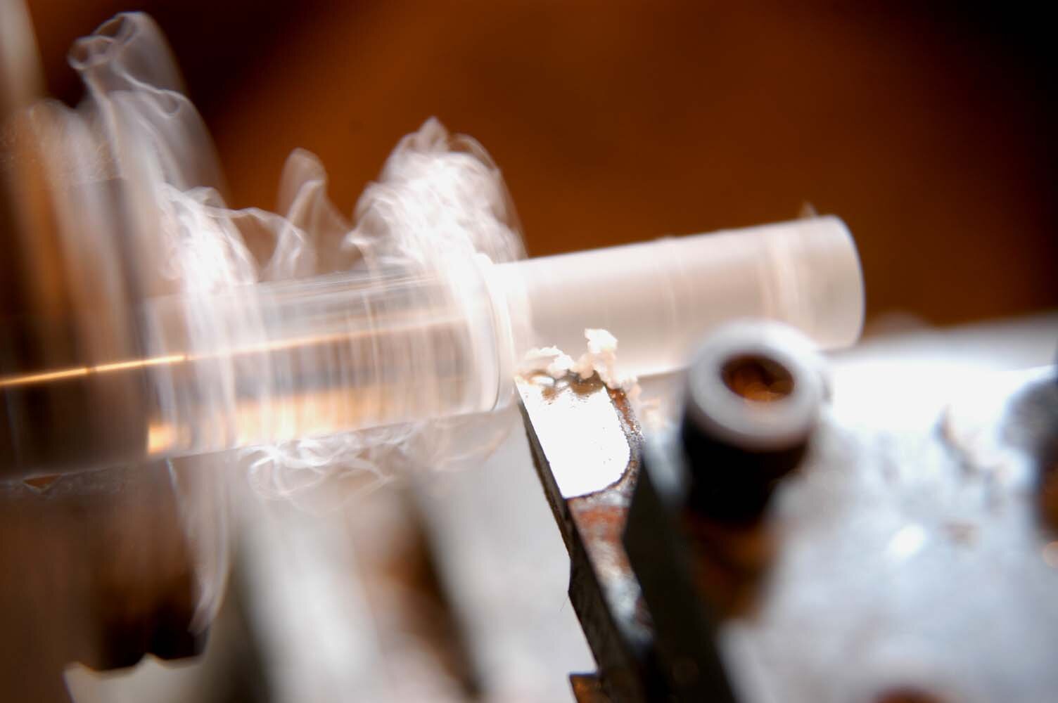
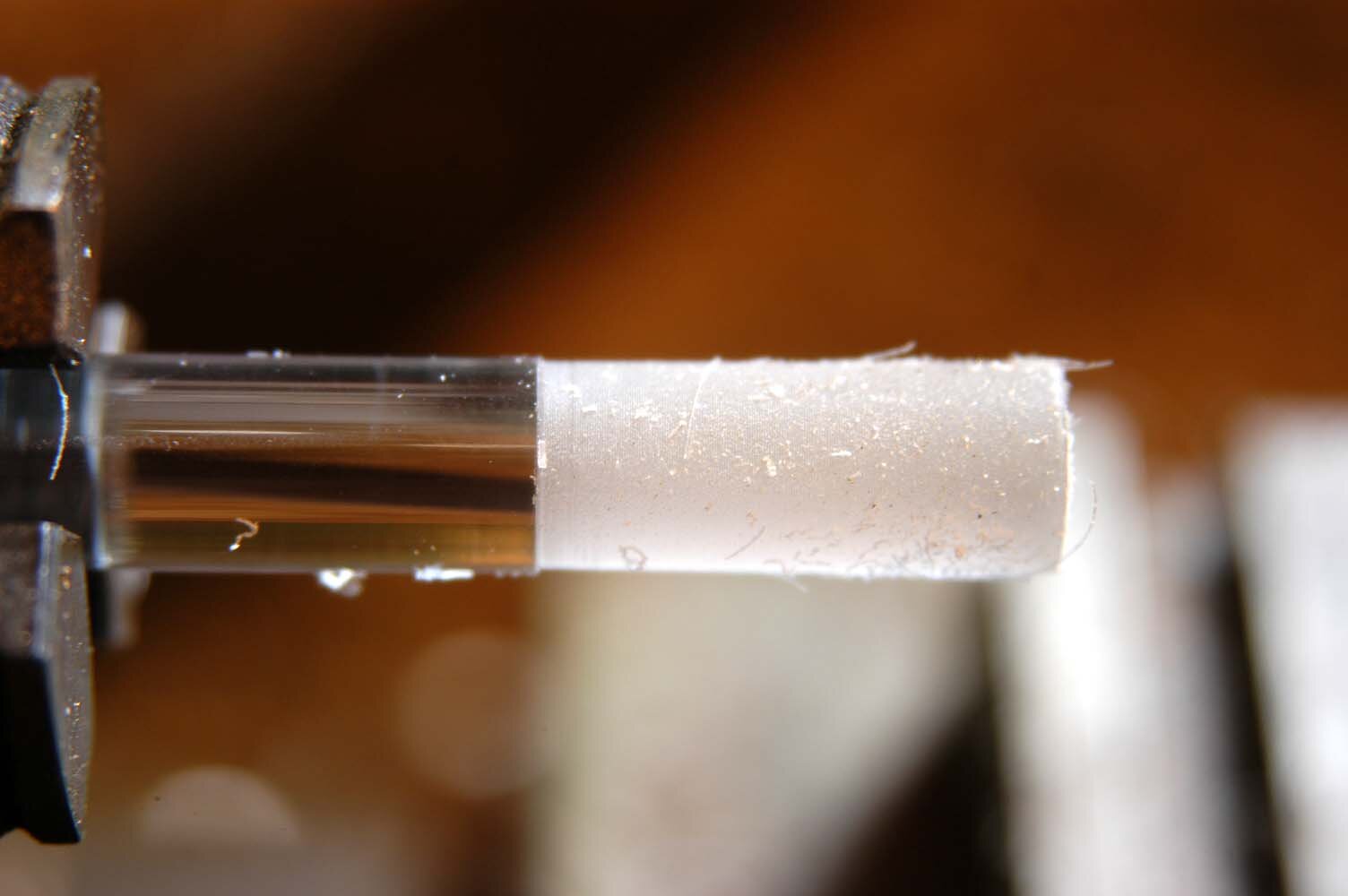
Viewing rod
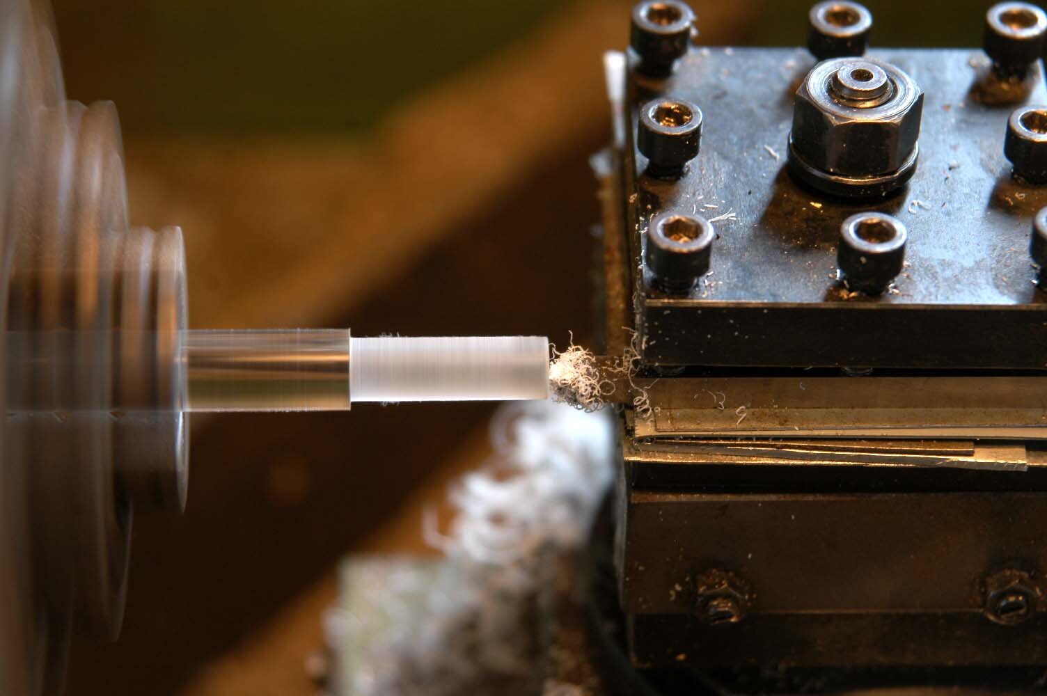
Cut a length of about 100mm from the clear acrylic rod and mount it in the 3-jaw chuck. Turn a 29mm section CAREFULLY to the exact 9.45mm diameter size. Again, a neat sliding fit is required for the punch to go into the body holes so GREAT care must be taken. A good micrometer is also required for this operation. The lathe revolutions must be low – about 250rpm – and the lathe tool very sharp as the acrylic rod can melt at very low temperatures. No heat can be allowed to build up, as it would if you used a high turning speed and a blunt lathe tool.
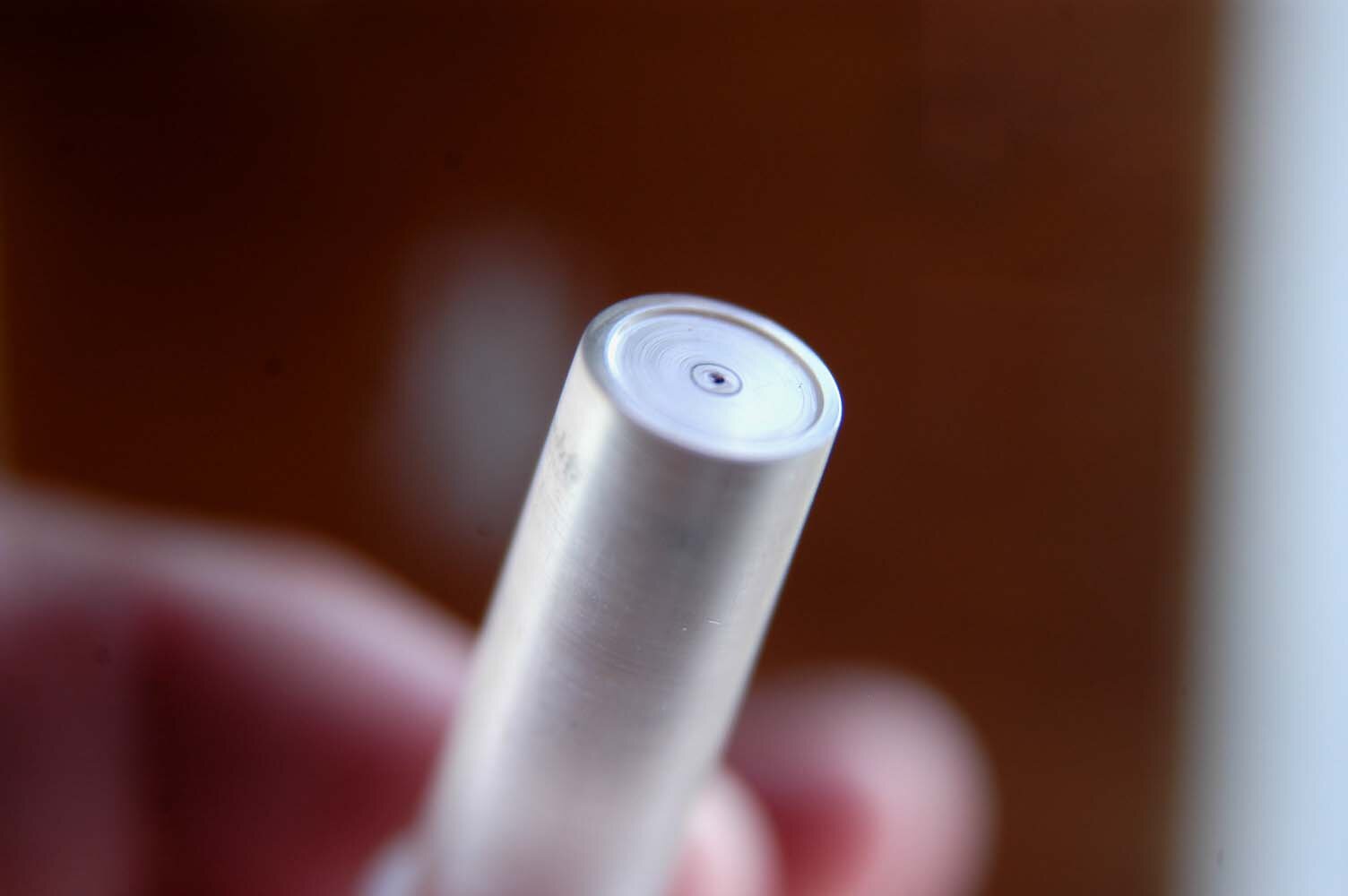
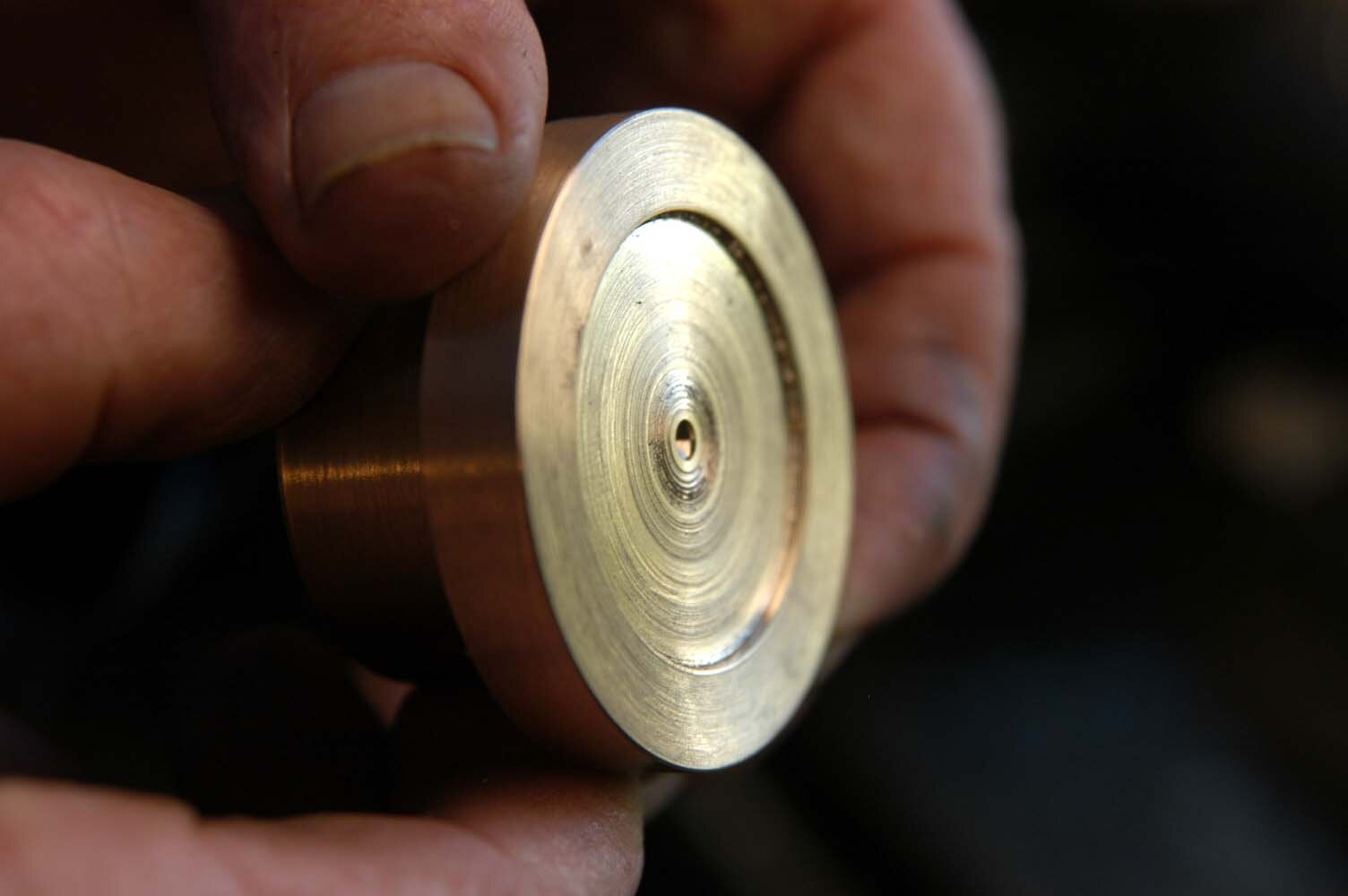
With the viewing rod still in the chuck and the lathe running at a low speed as above, very carefully turn the recess to the 1mm depth shown on the drawing. Then, using a very pointed lathe tool, scribe the 2mm diameter ring shown on the drawing for this part. The shallow and small indentation in the centre is put there using a No 1 centre drill (very small) mounted in the lathe tailstock.
While the viewing rod is in this position, polish the recessed end, first with 400-grit Wet and Dry sandpaper and then using the chemical household Brasso or Silvo till a reflective surface is obtained.
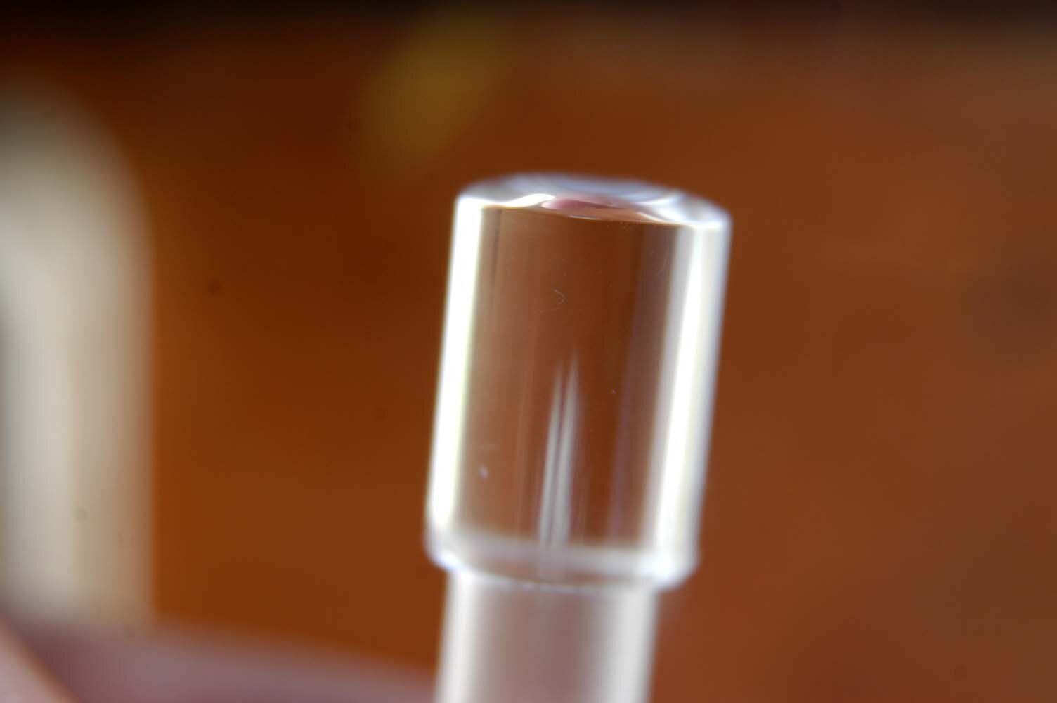
Curved viewing end
Part the viewing rod off or take it out of the lathe and cut to length, i.e. 46mm. Put the viewing rod back in the lathe with the largest diameter facing the tailstock. Using a clean, smooth file and low lathe speed, carefully shape a curve on the face so that the centre is approximately 1.2mm above the outer edge. Polish this face using 400-grit Wet and Dry sandpaper and polish with Brasso as above.
Marking dot
The “centre dot” and the “scribed ring” are required to be very carefully filled with black marking ink. Some experimentation may be required here; I used a Fine Line Marker pen that writes on glass and is available from stationery shops.
Testing
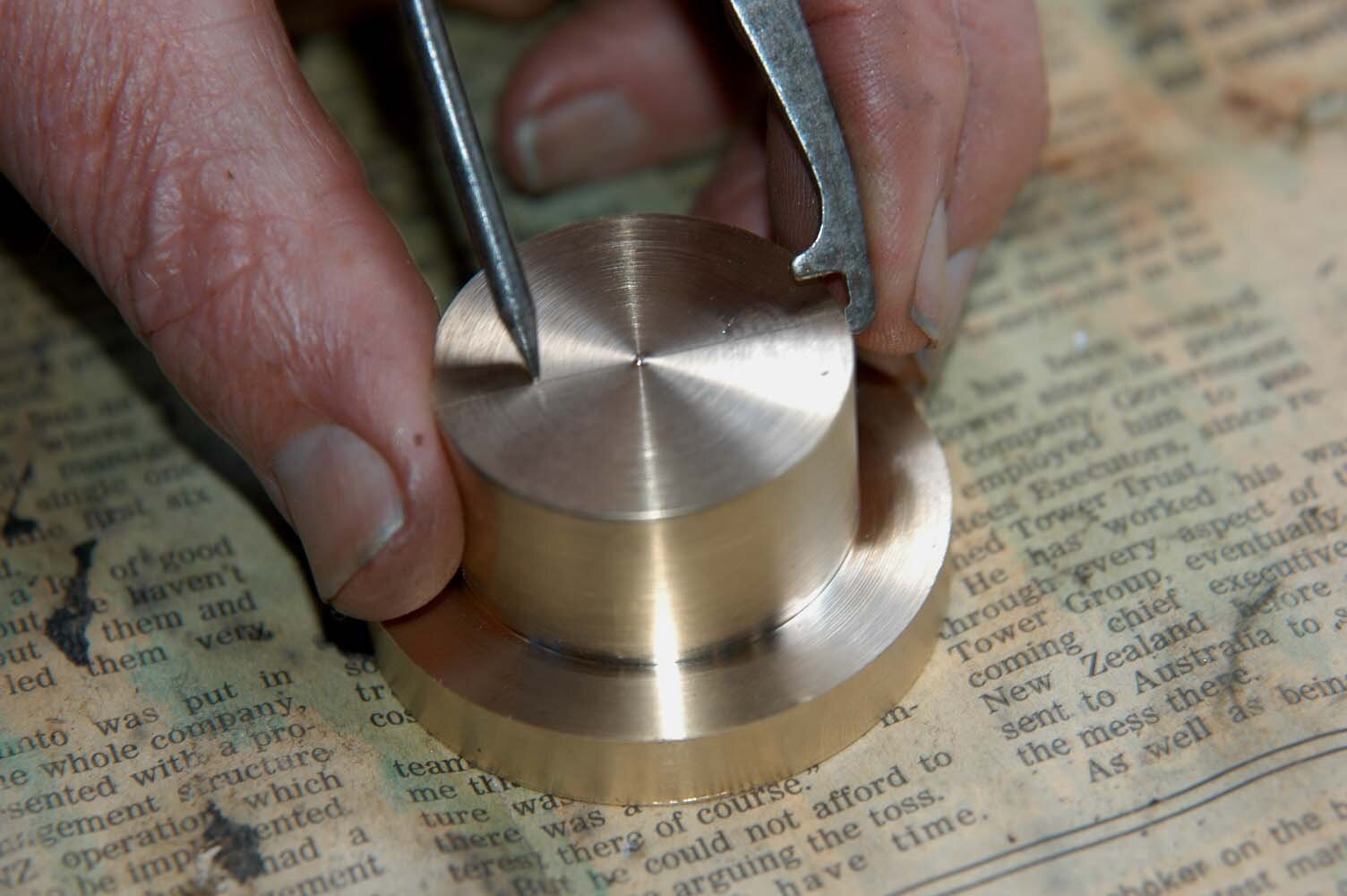
Test the use of the optical centre punch by blueing a piece of steel, and when it is dry mark a cross using a scriber and rule. Place the body over the marked cross such that one of the 9.5mm holes has the cross in the centre. Place the viewing rod on the 9.5mm hole and view the cross at a greater magnification.
Position the “centre dot” directly over the lines where they intersect and replace the viewing rod with the centre punch. Still holding the body in position, tap the punch with a hammer to indent the flat steel on the crosses centre. If the cross is hard to find through the viewing rod, the curvature of the top face is too great and requires flattening a little. This should only be required if the length dimensions and curvature instructions are not adhered to.
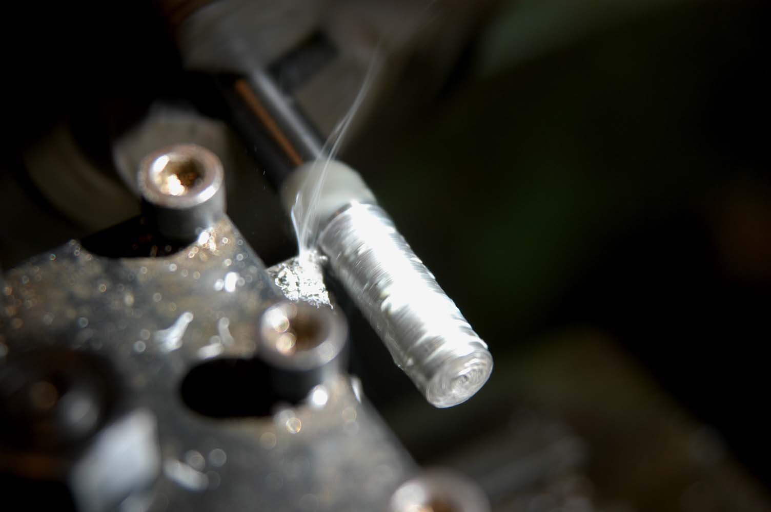
Note: The centre punch requires hardening before continued use. Fortunately, this is a relatively simple task. Broadly speaking, the steel punch is heated up to a bright red and plunged into special hardening oil or slightly warm water until cold. The punch is then taken out and the pointed end heated to a very, very dull red and slowly drawn back to a silvery blue colour.