Make a low-pressure, hot air engine
By Ross Purdy
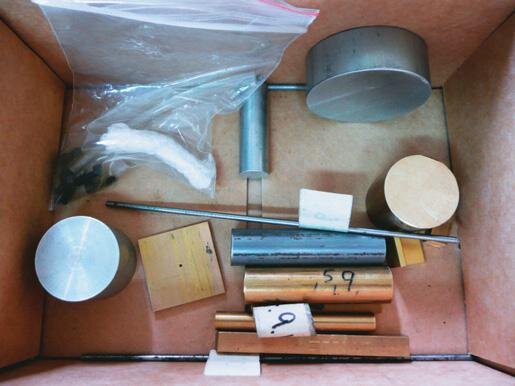
Several years ago I purchased a kit for a model Stirling engine from Mini-tech in Brisbane. I like to see the parts of an engine working and the transpar-ent cylinder here added a further dimension. The kit consisted of a set of 2D plans and a box of un-ma-chined stock bar metal. When I first bought the kit I thought it would be a bit of a mission to build and pushed it to the back of the cupboard. I recently decided to have a go. The kit only came with a set of drawings and some rudimentary assembly instructions.
The Stirling engine – how it works
The Stirling engine is a fascinating engine that magically converts an external heat source into rotary motion.
It was invented by a Scotsman named Robert Stirling back in 1816 as an alternative to the steam engine. The Stirling engine is safe, unlike steam engines, runs on low pressures and can be made quite efficient (up to 40 percent). Any source of heat will make it run—I’ve even seen one running on dry ice.
All you need is a temperature difference between the ends of the displacer.
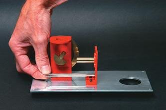
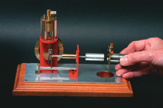
The engine I built has two cylinders. Heat is applied at one end to the displacer cylinder (A). The gas inside expands rapidly, rises through the plastic pipe to the top of the acrylic cylinder (B) and pushes the drive piston (C) down. At the same time, the crankshaft moves a displacer piston (D) inside the displacer cylinder (A) towards the hot end to “displace” the hot gas to the cold end of the tube (E). The gas cools there and contracts, sucking the drive piston back to the top.
This pushes the gas down the tube while the crank pulls the displacer piston back to the cold end of the displacer cylinder (E), shifting the gas from there to the hot end (A). The cycle repeats as long as the cold end of the displacer remains cooler than the hot end.
Ross Purdy with model engines and boat in his shed
Self-taught
I’m largely a self-taught model-engineer with a passion for making engines. My skills have come from reading books, asking questions of those more knowledgeable and lots of practice (and yes, making the odd mistake).
I began the construction of this engine with the two fabricated brass brackets for the drive cylinder and displacer cylinder, not easy as both were fabricated from several brass extrusions silver-soldered together.
Silver soldering
Silver soldering isn’t one of my favourite tasks in the workshop.
I have no trouble with soft soldering as it is so much more controllable. With hard soldering, I don’t like seeing the nice shiny parts I’ve just made oxidizing badly as they are heated to high temperatures. The next step is usually lots of elbow-grease to clean and polish the workpiece back to its former glory.
I don’t have oxy-acetylene, so trying to get enough heat into the job can be tricky, especially if it has a large surface area.
For small jobs, an LPG torch works fine and for the larger ones, I use MAPP gas (yellow cylinders).
To get the brackets soldered nice and square I just relied in the end on the fire bricks to prop the work up square while I soldered. The high silver-content solder-sticks I bought to do the job are more expensive but make the job easier as the melting point is lower. The trick to silver soldering is that you need only a tiny amount. When it hits the melting point, it will flow every-where (even where you don’t want it).
The easyflo flux is a liquid paste and you brush a small amount along the joint. I heat the work until the flux goes molten then when I think it’s hot enough, I touch the solder stick into the joint. If it is hot enough it will flow beautifully; it is one of those things you just have to practice. To clean up after hard soldering, I usually soak the workpiece in a solution of citric acid. This is easy to buy in crystal form from the supermarket and does a good job of cleaning up copper, brass, and steel.
Soft soldering
Both the drive and displacer brackets have further parts soft-soldered to them. These were a simple turning job in the lathe.
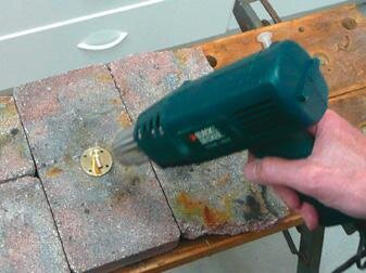
My secret to professional soft-soldering is electronic solder paste. These days electronic circuit-board components are soldered with a lead-free solder paste which consists of tiny solder balls in a flux. You can buy this in a syringe commonly used for rework and repair of circuit boards.
I put a tiny amount on the parts that need to be soldered together and remove any excess. The second secret is to heat it with a hot-air, paint-stripper gun on a fire-brick until the solder melts and flows around the joint. You can control the temperature very well and not discolour the workpiece.
I then painted the completed brackets with a spray of grey etch-primer to key into the metal (otherwise the paint chips off easily), followed by a spray of car primer/filler which works wonders in filling slight imperfections. I lightly sanded with 1000 grit wet & dry sandpaper before applying the top-coat colour. I go for two or three top coats with a light sand between each coat.
Base
Native New Zealand timbers add to the presentation of the finished model and I made the base, to which a 3 mm aluminium plate is fastened, from a nice piece of 20 mm matai.
For the hole for the meths burner in the aluminium plate and the timber base, I used a 38 mm hole saw for drilling, then a chisel and a hand router to bottom the hole to the correct depth. To add a professional finish to the edges of the base, I routed them with my favourite cutter. I drilled holes for the screw heads in the aluminium plate a little over-size, then for a very nice finish, I varnished the base with four light coats of an acrylic non-yellowing spray, sanding between each coat.
I completed this sub-assembly by drilling screw holes and polishing the aluminium plate, screwing the completed brackets to the plate, and the plate to the base.
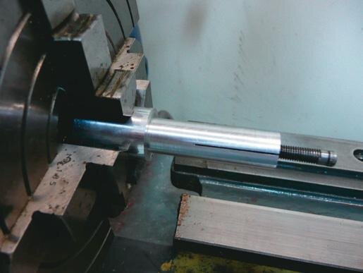
Crankshaft, flywheel
To make the crankshaft, the shaft and crank disc were silver-soldered together then machined to the final size. The counterweight was easily done by milling away each side while the crank disc was held in a machine vice. The flywheel is an easy machining job.
First I machine one side (usually the most complex of the two sides) and centre-bore it. This is then fitted to a shaft running true in the lathe and turn the reverse side and over-all diameter. This method produces a flywheel which runs nice and true on the finished engine. In the next step, I fit the crankshaft and flywheel to the assembled base and admire them.
How it comes together

Clear cylinder
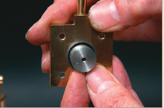
The next logical part was the clear cylinder which you need to make before the piston, so the piston can be honed down to be a perfect fit for the bore.
I faced and drilled then bored out the acrylic plastic using a boring bar to the correct size. While the cylinder was still in the chuck, I drilled the four bolt holes using a mill drill and a dividing head. The cylinder needs to be held from the internal hole and the outside turned to the required dimensions.
The easiest way to do this is to make a split mandrel fixture. I use a home-made tapered screw to clamp the workpiece securely. Acrylic (or Perspex) will polish up really quickly and easily with a bit of Brasso on a rag.
First, I sand with some 800 grit wet & dry then move up to 1000 or 1200 and then finish with the Brasso to get it back to crystal-clear again. The internal bore was polished using a Dremel with a 12 mm felt polishing wheel and the bolt holes were done with a pipe cleaner soaked in Brasso.
After all this polishing work, two flaws in the piece of acrylic supplied with the kit became evident. It looked like it had been glued together from three sheets which made it have two internal rings. I wasn’t happy with the look so I made a whole new piece from an offcut of plastic. This time it had perfect clarity.
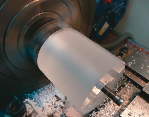
Polishing the acrylic cylinder
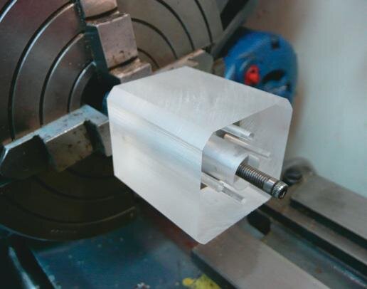
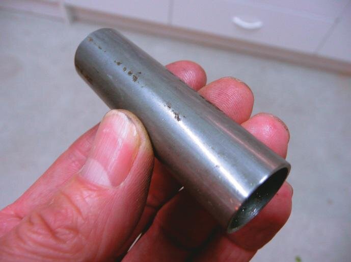
Tube turned for acrylic cylinder outlet
Displacer piston with threaded shaft
Connecting rod
As with all reciprocating engines, the connecting rod is straightforward to make.
You just have to bore both holes at the same time so they end up parallel to each other. The outside shape can be a bit fiddly to do but usually, a bit of milling and filing can produce a good looking conrod.
The piston has the gudgeon pin held internally via a yoke that is screwed into the top of the piston and allows the piston height at top dead centre (TDC) to be adjusted. The only tricky part here is to get the piston outside diameter (OD) to match the cylinder bore. The Stirling engine must have low friction and be gas-tight at the same time so the match of these two components is critical to the success of the engine.
Piston
I turned the piston down to almost the correct size, measuring with a micrometer as I went.
When the piston was a tight fit in the bore I began polishing the outside of it with 1000 grit wet & dry paper wrapped around a flat bar. It is a matter of polishing and testing frequently until you get the required fit; patience is a must for this process. The piston was a little tight at one point in the bore as plastic isn’t the most stable material to machine. I did a tiny bit more polishing of the bore with the Dremel wheel and Brasso fixed that problem.
The piston/conrod assembly was then fixed to the crankshaft and tested on the main bracket with the acrylic cylinder. With a bit of sewing machine oil in the bore, the piston traveled up and down very smoothly. I breathed a sigh of relief with all the hard parts successfully out of the way. Some tricky soldering remained but nothing that needed precision fitting.
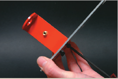
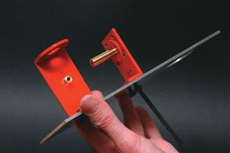
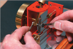
Displacer positioning jig used to drill accurate holes
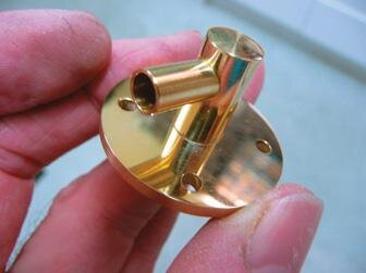
Cylinder head, air port
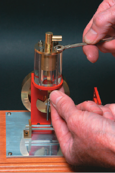
The drive cylinder head and air port were straightforward parts to machine and were soft-soldered together using my heat-gun method.
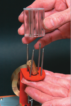
With this installed, the drive cylinder was completed. For a bit of light relief at this point, I made the burner and the two guide rods plus their support angle bracket before tackling the displacer cylinder.
Displacer piston
The displacer piston was made out of a felt-tip pen housing of thin-walled aluminium.
I unscrewed the pen tip, removed the felt, rinsed out the ink with meths. I took off the outside printing with paint stripper because I didn’t want it burning up in the hot displacer cylinder. I guess the idea of using the thin-walled tube was to keep its thermal mass low. Because it was so fragile, I decided the best way was to spin it in the lathe and slowly score it with a sharp-pointed tool. This turned out to be very successful and cut through the wall without damaging the tube.
A threaded aluminium insert was Loctited into the tube to complete the displacer piston. Remember the piston has about 1.5 mm clearance around the bore, so no special fitting is required. The piston is screwed onto a long rod which is driven by the main crank-shaft. The rod with the kit was an odd size (around 3.1 mm) and was scored with a spiral the entire length. I replaced it with a 3 mm silver steel rod. The displacer piston sleeve was therefore reamed 3 mm and the rod threaded at one end so the displacer piston could be screwed on. What was required was a nice low-friction, gas-tight fit between the rod and sleeve.
Raw displacer cylinder
Displacer tube machined on split mandrel for…
…polished finish
Puzzle
The displacer cylinder was a bit of a puzzle as the drawings were a little confusing.
What was required was to turn the 18 mm inside diameter (ID) tube down to have a wall thickness of just 0.5 mm except where the heat-sink was located.
Again the best method was to run the tube on a split mandrel so the pipe ID was running true. After all, I wanted the 0.5 mm thickness with respect to the inside, not the outside, of the pipe. The cylinder then had to be hard-soldered squarely onto a flange at one end and a cap to the other. I thought the cap would be easy but I had more trouble soldering it on than any other item on the engine.
I didn’t want solder flowing on the outside of the work so I cut a couple of pieces of silver solder-stick and put them in the inside with some flux. I heated up the tube and cap, hoping the solder would melt inside and wick up into the joint.
On the first attempt, I obviously didn’t get enough heat and the cap fell off when I was cleaning it up. My second attempt with a bit more heat finally did the job. I made the tube a good fit in the flange so that it would hold itself square while I soldered it.
Now the displacer assembly needed to be fitted to the bracket with the bore in the centre of the piston-sleeve. To do this, I had to make a dummy piston the right size for the bore that screwed onto the 3 mm piston rod. This located the displacer assembly while I spotted the bolt holes. The holes were drilled and threaded M5, completing the dis-placer cylinder.
Silver soldering the bracket using MAPP gas
Yoke, heatsink
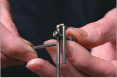
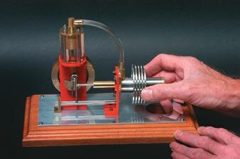
Only two more components needed to be fabricated to complete the engine, the yoke and heatsink .
I was dreading making the yoke as it was made out of three small pieces of 3 mm rod, all hard-soldered together then hard-soldered to the displacer-piston rod.
All this had to be square and parallel. Because it was only 3 mm rod, I could use my butane torch which has a much smaller and more controllable flame. It turned out to be very easy to do. I find that so many times the parts which look difficult aren’t and the easy ones give you all the grief.
The last part to make was the large round aluminium heatsink. I like making components with fins on them as they look so cool when they are finished. It does take quite a bit of parting-off to plunge the lathe cutting tool deep into the workpiece so lots of cutting fluid is required.
I learned a while ago to always cut the fins in one direction (i.e cut, move, cut, etc) and never go back and try to tidy up one you have already done as you can’t seem to get the tool back in exactly the same place. This part was quite difficult to make because the kit came with just enough material for the overall length. There was nothing to hold in the chuck; so a bit of extra material would have made the task so much easier.
As it was, I had to make another split mandrel to try and hold it but it was very difficult to get any drive to it while cutting those fins.
Just as you started to get into cutting the fins, the tool would cause the piece to rotate on the mandrel. If I had to make it again, I would get a longer piece of metal, for sure.
Displacement piston sleeve and air port
Connecting rod marked out, jigs for rounding ends
Finished conrod
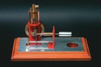
Running
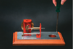
Now all the parts were together and everything looked about right so it was time for the big test: would it run as an engine?
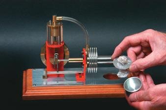
I half-filled the burner with meths and lit it. After a while I tried flicking the flywheel. The engine looked like it wanted to run but would do less than one revolution and stop. Once it had cooled down, I started to go over the engine trying to find out why it wouldn’t run.
I noticed that at one point in the revolution it seemed tighter than normal and it was my guess that this extra friction was enough to stop it from running. To find out why I disconnected the displacer piston and found the problem had gone away so it was somewhere in the displacer arrangement. I thought it must have been in the rod and sleeve although that also seemed fine.
With the displacer cylinder removed, I could see everything was OK there as well. So the problem had to be in the sliding yoke.
I removed the crank-pin 5BA bolt and tried it in the yoke slot, thinking maybe it was when I soldered the yoke together that I didn’t get the two sides parallel. The bolt slid up and down beautifully, but then I discovered the bolt wouldn’t rotate without binding. Wait, I thought, the bolt isn’t round. I mounted the bolt in the lathe using a collet and turned a tiny amount off turning it from an ellipse into a circle.
The engine was reassembled and turned perfectly by hand this time through a complete revolution. I fuelled up the burner again and lit the wick. After about 30 seconds, I gave the flywheel a flick and presto, away it went.
I always get a thrill at seeing one of my engines running for the first time. It was especially true for this one because I had had no previous experience in making such an engine. The engine runs at about 600 RPM with a good differential between the hot and cold ends of the displacer tube. Over time, the heatsink gets hot and the engine slows but by this time the burner is out of meths anyway. The lesson learnt building Stirling engines is when they say “low friction” they really mean LOW FRICTION.
I hope this will encourage others to have a go building one of these fascinating engines.
Machining heat sink on split mandrel
Milling slot in back of heat sink
Finished heat sink