How to modify a pipe bender for flat steel
By Peter Byam
Recently, I bought a hydraulic pipe bender online, that will bend standard pipe up to 50 mm diameter.
This tool, found in many well-equipped workshops, is purpose-made for bending pipe.
A curved tool mounted on the top of the jack spigot holds the pipe. The pipe is bent in the middle as the jack pushes upwards and the two ends of the pipe are stopped against the rollers at the end of the plates. But a pipe bender has no other use and that is too bad because it is a large expensive tool.
I wondered if the heavy 12-ton bottle jack could be used for some other purpose. Once I had inspected it, it seemed reasonable to modify the bender so that it could be used to bend flats as well as pipe.
The answer was to drill the side plates to incorporate pins on which two new rollers are placed close to the middle.
A piece of flat held on top of a specially created tool mounted on the jack spigot is pushed up against these rollers and bent as the pressure continues upwards. This makes the bender a dual-purpose tool. It is so obvious that I am surprised I have never seen or heard of this being done. This modification is simple in design but critical to make.
Holes for new rollers and their pins must be laid out and drilled exactly as shown in the drawing pictured here, centred on the hydraulic jack. No room for error here. You have only one chance to get it right. Pump the jack up to the top of the frame. Lay a square across the top lined up with the centre of the spigot. Mark both plates on the top edge. Repeat using the square turned over and end-for-end. The average of the marks should be on the centre of the jack. Using the square, strike a vertical line down the front and the back of the frame.
Check that the tops of both plates are the same distance from the base of the jack. Double-check your work; if all is well, mark in all the centre lines as shown in the drawing. Lightly centre-punch the eight-hole positions.
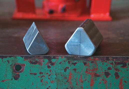
Successfully bent flats
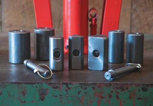
Top of bender showing 65 mm rollers in place
Pins
The pins supplied with the bender were too loose to use so I made new pins.
I increased the size of the holes to 20 mm in diameter. To do this, remove the heavy jack and clamp the frame to your mill or drill press.
Use a centre drill first and then drill four holes at low speed with cutting oil. Turn the frame over and drill the remaining four. Clean up the holes and reassemble the bender. I made the two rollers from 65 mm round mild steel but 50 mm rollers are also useful for 10-12 mm flats. They leave a wider gap for easy bending. I think a 50 x 12 mm mild steel flat should be the maximum size to bend, although wider flats can be bent if they are 10 mm or less.
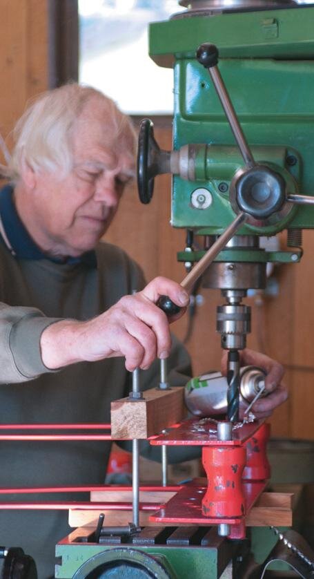
Peter using 1937 South Bend lathe. “My Dad bought it for me when I was eight and I have used it ever since”
My version
My bender measures 95 mm across in-side the plates, but they can be sprung out for 100 mm flats. The rollers are drilled 20 mm diameter and the pins are turned between centres to a close, rolling fit.
Cross-drill the pins 8 mm for AG 2.8 mm cross pins. The most useful tool to fit on the jack spigot is one that will form an inside radius of about 5 mm.
I made one from the same 65 mm round that I used for the rollers. For this, a flat is milled or turned on the bottom where it will rest on the shoulder of the jackshaft, and a hole is drilled to closely fit the spigot. Mark out the radius at the top and cut away both sides to allow for a bend, a little past 90 degrees. This can be done by milling or with a hacksaw—slowly and with skill.
A large-radius tool can be simply made from a 45 mm diameter round which is just large enough for the spigot hole. It is likely you will want to experiment with various rollers and tools to get the exact bend you want. Use the top holes for thick flats or bar and the bottom holes for thinner material.
Caution
I originally drew the top holes at 60 mm each from the jack centre and the bottom holes at 50 mm each from the jack centre. But I realised that for thinner flats I would need to make much larger rollers as well.
It was easier to redraw the top holes at 50 mm each distant from the jack centre and the bottom holes at 40 mm each from the jack centre (see drawing).
Pin turned between centres
Facing the end of a 65 mm roller, 20 mm drill
Small bending tool with sides cut with a hacksaw (slowly, and with skill)