Build an ingenious water ram to run water uphill
By Brigit Manning
WATER HAMMER
The water ram works because of a phenomenon called “water hammer” as this generalised diagram below shows. A continuing flow of water down a drive pipe (2) from a higher water source (3) eventually builds up enough pressure to close a solid waste valve (1) with its force.
The water in the body of the water ram (5) stops and the back-up pressure now forces open the delivery valve (6) to an air-chamber (7). The air-chamber cushions both the pressure wave and stresses caused by the waste valve suddenly closing which creates the water hammer.
As the pressure in the air-chamber begins to exceed the pressure in the outlet or static delivery head, water is pushed up the delivery pipe (8).
Because water is being sent a greater distance up the delivery pipe to the end point than it is coming down from the water source, the delivery pipe becomes static and falls back.
Air trapped in the air-chamber has been compressed under pressure and forces the delivery valve closed. With water flows static, the reduced pressure in the body of the water ram allows chamber the loaded or sprung waste valve to reopen and the process begins again.
Jan van der Linden arrived from Holland as a new immigrant with marine engineering skills. He had been led to believe that Moerewa was the New Zealand equivalent of Germany’s industrial Ruhr district, and was astounded when he arrived to see only two smoke stacks, one from the dairy co-op factory and one from the freezing works.
Jan worked for 27 years as a refrigeration engineer for AFFCO in the then-lively township, in his words “with never a dull moment, as the Kiwis say,” and settled in the district. It was the lake that attracted Jan and his wife Carla to their beloved 4.5-hectare Bay of Islands property where they are now retired. No doubt it was their Dutch heritage that lead Jan to build windmills to irrigate the trees they planted.
But while the long, dry summers created a need for irrigation, their sheltered site did not have enough wind to drive the two windmill designs. Then another solution presented itself. The lake that would become a dry bed each summer had a reprieve when the Acclimatisation Society dammed it and Jan quickly realised it had enough water to channel down a drop to drive a water ram for irrigation.
Jan knew water rams had been widely used in New Zealand but had never seen one, although he understood the principle – that they work because, unlike air, water is incompressible. The first water ram was patented in 1772 by Englishman John Whitehurst. Designs have evolved since then and continue to do so particularly in Holland where, in the 1990s, one university was building 20 water rams a year for third-world projects.
Water rams use the kinetic energy of water flowing downwards to push a small portion of the flow uphill to higher storage areas or land (see panel). They are well-known in third-world countries as a basic technology for diverting water because they are mechanically simple and very reliable, needing minimal maintenance and having a long life.
(above) Pulse power of water ram. Pressure on orange ball blocks exit, diverting water to delivery pipe from pressure chamber. Eventually, as ball falls back again, water pulses out of exit hole. Process repeats.
Jan worked out his first design with only his understanding of this principle as a starting point. He now believes that working in isolation was to his advantage, since his original design is simpler, quieter and more efficient than others he has seen since.
Jan’s novel idea was, instead of a conventional valve, to use a marble that closed against an O-ring within the ram chamber. The O-ring is compressible and this eliminates most of the noise usual with water rams.
Rural engineer Maurice Denton of Tokoroa who services water rams in remote areas from time to time agreed that the O-ring valve was a considerable improvement. He said that, especially over the last 20 years, farmers ran more stock and needed much more water at high pressure to accommodate equipment for dosing. In these cases, water rams were not appropriate but in remote areas where there was water flowing to waste, they worked very well.
The marble glides up and down the ram chamber on guides or metal rods. The marble / O-ring valve closure allows the exhaust flow to progress straight on out of the ram chamber, rather than being diverted sideways by a conventional valve movement with a resulting loss of efficiency.
“Straight through has the advantage of allowing maximum speed to develop, which is so crucial in the equation of kinetic energy,” Jan says.
Key parts
The water flow must provide a drop of at least one vertical metre, the steeper the better, although Jan’s first design worked very well with a drop of 0.3 metres and a 20 mm drive pipe.
His current system to collect the water flow from the lake has a drop of between two and three metres using a seven-metre long, 50 mm alkathene drive pipe but a steel pipe with less elasticity could be better. The alkathene pipe vibrates constantly and Jan uses an alkathene sleeve as protection against chafe. The delivery hose is usually a 25 mm alkathene irrigation pipe.
The distance and height to which water can be delivered depends on the amount of pressure generated by the drive pipe and ram housing. Jan’s current water ram pumps 3600 litres a day up around 20 metres over a distance of approximately 600 metres.
Jan has installed the water ram housing to slope upwards at about 45 degrees. This orientation is essential for the secured ram to work correctly. A nipple on the under-side of the housing delivers about 10 per cent of the water from the drive pipe via a 20 mm non-return valve into the surge vessel or air chamber. The remainder of the flow exhausts directly out of the ram housing when the pressure pulse passes and the marble drops to the drive pipe end of the ram housing.
To avoid loss of efficiency through a bottleneck, the cross-section area inside the ram housing minus the cross-section of the marble must be about the cross-section inside the drive pipe.
The surge vessel or air chamber converts the pulsating flow from the delivery nipple into a more-or-ram housing when the pressure pulse passes and the marble drops to the drive pipe end of the ram housing.
To avoid loss of efficiency through a bottleneck, the cross-section area inside the ram housing minus the cross-section of the marble must be about the cross-section inside the drive pipe.
The surge vessel or air chamber converts the pulsating flow from the delivery nipple into a more-or-less constant flow. For many years Jan used the canister of a five-litre, hand-held garden sprayer with a three-litre wine carton bladder blown up inside and a bucket to keep the sun off it.
Jan recommends using a 15 mm shut-off cock in the delivery hose to simulate back pressure to give the ram a regular pulse. Closing the cock creates a pressure increase and the pump starts to work with constant rhythm.
Intake cap.
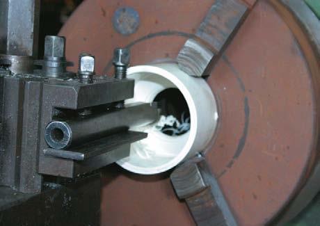
Create rebate for O-ring.
Jan continues to refine his design – the Mark 8 version pumped 1000 litres per day more and 80 vertical metres higher than the Mark 7 version. He is up to Mark 9 and his design using readily available materials is easy to replicate and inexpensive. The $2 shop provided the most recent find of a perfect 50 mm glass sphere in the form of a toy globe. This was an improvement on the previous marble which was pitted by coloured decorations.
Jan eventually hopes to find a waterproof, incompressible 50 mm plastic sphere such as an acetyl ball which will be lighter than glass but still heavy enough to sink in water. He used a steel ball bearing once and it worked perfectly but wore out the guides in the ram chamber within a season. Water rams in general keep going without maintenance and some have been operating here unattended for decades. Maurice Denton has serviced a water ram put in 100 years ago by early settlers. It still supplies the Conservation Department offices and camping ground at Stony Bay in the Coromandel.
Much of Jan’s ingenuity goes into deterring eels from blocking the drive pipe. A plastic canister punched with lots of holes now protects the intake. Installation in moving water can also be tricky and he has used strings, stones and recycled handbags to secure the water ram correctly for position and angle and to prevent chafe. The trees are now a well-established a feature of the van der Linden’s immaculate property and it’s clear that they no longer need watering through the summer. However, Jan is not concerned that his ram development may no longer be driven by necessity.
“As long as the Lord gives me wisdom in the evening and inspiration in the morning, I will find some-thing to do,” Jan smiles.
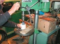
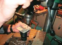
Drilling cap with jig.
Countersink cap holes
Water ram part-assembled. Note O-ring in cap
Water ram assembled
Making the water ram
First find your two-inch marble which must be heavier than water. Glass is better than steel which quickly wears out the guide rods. The water ram can be put together and installed by anyone with a talent for accuracy, basic tools including a drill press and either a lathe or a friend with one.
The Hansen 50 mm hose tail has the 50 mm alkathene drive pipe hose secured to it with a stainless steel hose clip. The threaded portion of the hose tail is cut off, exposing the eight-sided flange in the middle. The threaded stainless steel rod is cut into six equal lengths to form guides inside the water ram for the marble. They must be fitted into accurately positioned holes drilled into both end caps so the marble moves freely inside the sections of rod and won’t jam.
To locate centres for the pilot holes, on the outside of an end cap scribe a circle with diameter 50 mm plus 7 mm. The 7 mm allows for the width of the rods plus a half millimetre clearance. Divide this circle into six equal arcs and drill pilot holes at these points. Do the same for the other end cap. Scribe the same-sized circle onto the hose tail flange, divide it into eight arcs positioned in the corners and drill pilot holes at these points.
On one end cap, drill 6 mm holes at each pilot hole and counter-sink these to 45° from the outside. Mark this as the discharge or delivery end cap. The other is the drive pipe end cap.
Jan’s water ram has two guide rods screwed into the hose tail flange while the remaining four screw into the drive pipe end cap. He takes the hose tail flange and at two opposite pilot holes drills out 5 mm holes and taps these to 6mm. He drills four 5 mm holes at the remaining pilot holes in the drive pipe end cap and taps them to 6 mm to secure the other four guide rods . Screws secure the drive pipe end cap from the inside to the flange. At the remaining six pilot holes on the hose tail flange, drill 3 mm holes and tap these to 4 mm. Drill 4 mm holes at these points through the drive pipe end cap and countersink from the inside of the drive pipe end cap to around ± 45°. The drive pipe end cap finishes up with six large and six smaller holes through it.
For the water inlet and discharge holes, drill a 33 mm hole in the centre of the drive-pipe end cap and a 44 mm hole in the centre of the discharge or delivery-pipe end cap. For the delivery hole which accommodates the PVC nipple, drill a 20 mm hole in the side of discharge end cap.
To seat the O-ring, you need a re-bate within the discharge end cap. Using a lathe, or asking someone with a lathe, completely rebate the O-ring within the rim of the 44 mm discharge hole. The rebate should be ½ to 1 mm narrower than the outside diameter of the O-ring to hold it securely.
A sleeve is positioned around the steel rod guides to reduce eddy currents which can prevent the marble valve from closing. Jan formed the 100 mm PVC pipe into this sleeve which is slit on one side from top to bottom. The sleeve was squeeze-loaded into the discharge end cap and the other end cap fit-ted over it.
Jan limited the travel of the ball inside the water ram by inserting a limit pin cut from a 3 mm stain-less steel welding rod. He drilled a 3 mm hole through the drive pipe end cap, 45 mm from the edge and used epoxy resin to secure and seal the pin in it.
Pete Chandler gives a final tighten.
Warm water softens delivery pipe pre-fitting
Pete Chandler’s bush assembly.
Jan van der Linden and early water ram model
Assembling
Glue the hose tail and drive pipe end cap together with epoxy resin, a better bonding agent for the different materials here than PVC cement. Screw all the stainless steel rods and the six stainless steel screws into the holes provided, making sure to create a good seal with the resin.
Slip the electrical shrink tubing over the stainless steel rods and shrink to fit. This makes for silent, smooth movement of the marble. Jan here uses inner tube for six rubber washers to seal the holes for the rods in the discharge or delivery pipe end cap. He cut a seal to fit between the two end caps and fitted it around the spring-loaded sleeve. Place the marble within the rods before fitting the discharge end cap over the stainless steel rods, placing it firmly against the rubber seal and securing each rod with a rubber washer, a stainless steel washer and a 10 mm stainless steel nut.
To complete the ram housing, use PVC cement to glue the 20 mm PVC nipple into the delivery hole. Allow plenty of time for the PVC cement to cure properly.
Screw the brass non-return valve to the PVC nipple. Screw in the brass T to this valve. Connect the surge vessel to the reducing nipple and screw this into one arm of the brass T. Attach the delivery hose to the other arm of the T. A stainless steel hose clip secures the hose tail to the drive pipe.
To start the ram, Jan first fills the drive pipe with water then pushes the marble off the O-ring into the housing with his fingers, taking care not to unseat the ring or jam his fingers. The water flowing in from the drive pipe will push the marble back up again. Jan pushes it open again until enough water has been pumped into the delivery hose to provide the required back pressure to open the marble valve by itself.
Jan van der Linden and early water ram model
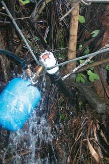
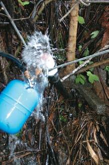
Jan van der Linden runs his water ram test
PETE’S VERSION
Pete and Libby Chandler run a venture getting tourists down into the Waitomo Caves.
But earth scientist Pete has been wanting for ages to take things upwards on his King Country land. He has been intrigued by the classic Third-World technology water ram. He has wanted to use it to pump water from his farm stream, with up to five metres of head in the drive pipe, to a stock tank at the top of his five-hectare property. Modifying Jan van der Linden’s clever design (see main story) to suit his material and progressive findings, Pete Chandler found the best way to put the holes in the curved end caps was to use a template made from a piece of tin.
“It’s tricky when you have to countersink, but the reason is to have the washer pull the whole mechanism in tight,” he says. He says it’s easier to cut holes around the cap before the large hole in the centre.
He also adjusted the different 33 mm and 44 mm end holes in the end caps to be two uniform 44 mm holes.
Pete Chandler’s version of Jan’s water ram design, showing essential parts
(clockwise)
Drill out cap with Forstner bit
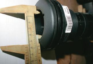
Measuring hose tail pipe
Drilling hose tail flange
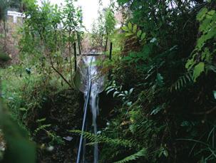
Stream inlet
He removed some rubber shrink wrap protecting the threaded rods to allow the billiard ball to travel up and down more easily inside the water ram. He substituted some plastic washers for the inner-tube rubber washers recommended when he found they didn’t seal well. He also had a local engineer rebate the groove in the end cap for the O-ring.
Pete fabricated a “self-clearing sieve-pipe” out of two pieces of 80 mm Marley downpipe, taking it out four metres horizontally to give a steeper drive pipe intake.
One test showed the water ram pumping up the adjacent hill at one litre in 52 seconds or 70 litres per hour, or 1660 litres a day. There is a good bit of surplus pressure, he says. Pressure problems have been tracked to small sticks and stones in the pressure vessel or dirt behind the O-ring.
“The water arrives in pulses, and there is a background, low-frequency thumping noise that would be noticed by anyone passing, but it’s not as bothersome as a steel water ram I observed at Fieldays.”
Pete Chandler’s top tank fed by water ram
MEASUREMENTS
Metric measurements used in this article are those of standardised fittings and not necessarily the exact metric conversion of imperial fittings originally used by Jan van der Linden.
For example, this means 15 mm not 13 mm for ½ inch and 20 mm not 19 mm for ¾ inch.
PARTS LIST
50 mm alkathene hose hose tail
rubber O-ring
2 x PVC end caps
1000 mm x 6 mm stainless steel (s/s) threaded rod
6 x s/s washers
6 x 10 mm s/s nuts
6 x 4 mm s/s screws with counter-sunk heads
electrical shrink tubing
100 mm of 3 mm thick PVC pipe @ 75 mm outside diameter
car tyre inner tube
PVC nipple, 20 mm screw-fitting reducing to 15 mm
PVC cement
epoxy resin
20 mm brass non-return valve
20 mm brass nipple
20 mm brass T
air chamber / surge vessel with 50 mm connection
brass reducing nipple, 25 mm to 20 mm
s/s hose clips
3 mm s/s welding rod

