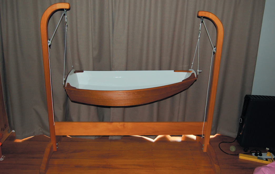
This Cradle Rocks
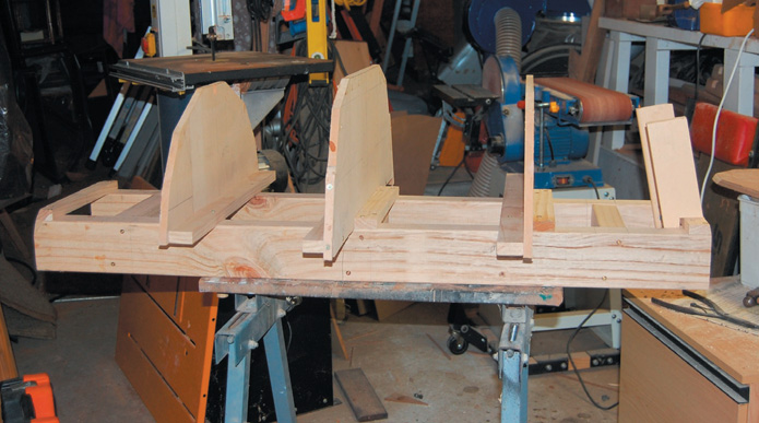
Jig on pine ladder
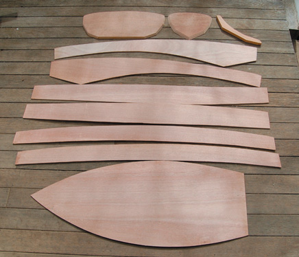
marine ply for panels, bow and stern
When I got the news that I was going to be a father of a baby girl I thought that maybe I could get out of redecorating the baby’s room if I embarked on a special project under the house. The idea of building a cradle boat was inspired by photos in an old magazine so I went bought a copy of The Expectant Father’s Cradle Boat Book. But the boats were either very basic or so intricate I’d be lucky to finish it in time for her 21st birthday. Then I thought about scaling down plans of a small dinghy I had built. Designed by Joel White and called the Nutshell Pram, it had a flat bottom and three side-planks making it both stable and relatively easy to build. At first glance, these old imperial-measurement plans seemed ideal to convert into a cradle.
The original hull had a laminated midship frame and a prominent internal fore-keel that would have made sleeping aboard quite uncomfortable. But as it was not going to be a seagoing boat, the frame was left out and the fore-keel modified to reduce the head-hitting potential. The next problem was how much to scale the plans down by. I settled on a half-sized model of the 7’ 7” (2.3 metre) original which, although in hindsight was a bit large, was less of a headache to scale. As my tape measure and my brain work better in metric, I wore out the buttons on my calculator plans converting all the measurements. For materials, I used 12 mm marine ply for the bow and stern and 3 mm marine ply for the bottom and sides. This made the planking flexible enough to shape easily and gave the bow and stern a substantial cross-section for gluing and taking the temporary screws. The other pieces were made from timber I had lying around.
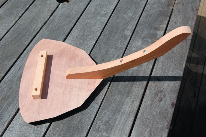
Fore-keel glued and screwed to bow
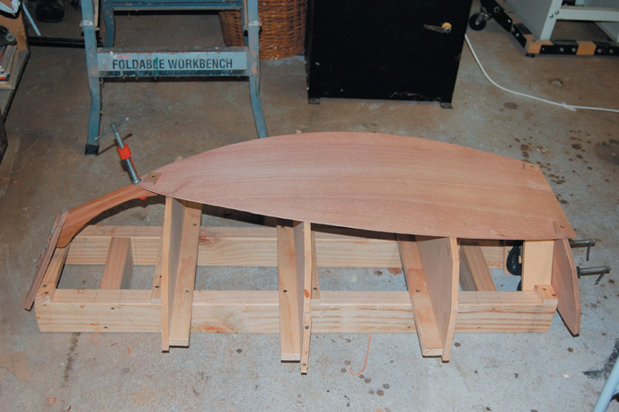
Bow,stern and base panel in place
The knees were made from planed-down old weatherboard that had a lovely fine grain. The gunwales were made from cedar. I used two-pack epoxy glue for assembly. It is a bit messy to mix but it makes a very strong bond and is easy to sand after. I transferred the measurements onto the plywood panels to form a pattern of points that were joined up using a batten to form a smooth curve. The panel shapes were cut out with the band sawand trimmed to shape.
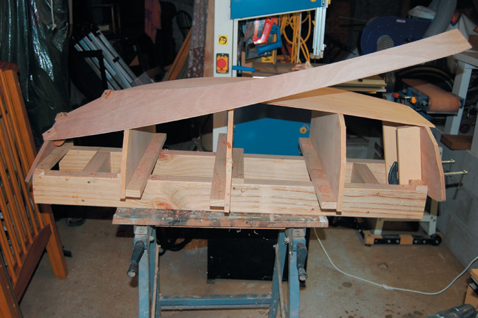
The boat is built upside-down on a temporary jig which gives the shape to the panels while they are joined together. Once assembled, the shape of the curved panels give the hull its rigidity and the jig can be removed.
The jig was made from MDF frames mounted on a pine ladder, built to half scale of the original. The main difference was that the centre-frame was made from MDF instead of laminated and attached to the hull. To stop drips of glue accidentally sticking panels to the frame, I covered the edge of the frames with packing tape.
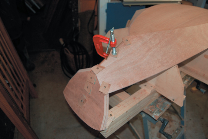
The internal fore-keel ties the bottom, lower side panels and the flat bow panel together and helps locate the bow in its correct position on the jig. To prevent baby’s head from banging into it, I made the keel in two parts with the bulk of the keel able to be removed once everything was together. The fore-keel was glued and screwed to the bow panel and located in a notch in the forward frame of the jig. The stern panel was located on the jig against two uprights and held in place with temporary screws and brackets. Once the bow and stern panels ware attached to the jig, I carefully placed the bottom panel on the jig and held it in place with temporary screws, using scrap plywood pieces under the screw-heads to avoid damaging the panels. Then I glued it into place.
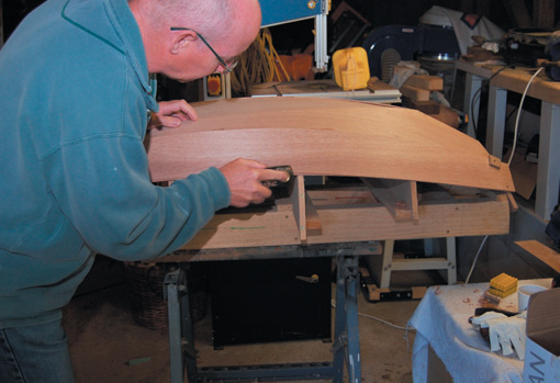
When the glue had set I used a small, freshly sharpened blocking plane to bevel the bottom panel to accept the first side panel or garboard. The bevel changes along the length of the panel so I used the angle of the frames as a guide, offering up the next panel to check for the fit.
The aim was to end up with no humps or hollows, the panel fitting well and a feather edge on the inside. I also bevelled the forekeel to suit the garboard panel, blending it in with the bevel on the bottom panel. After checking, I glued the panel and held it in place with temporary screws. Cleaning up the excess glue as I went saved time later on. To allow for variances in building, the panels overhung the ends but I trimmed them flush once all the planks were glued. Rather than work down one side then the other, I fitted the other garboard to help keep the loads on the jig even.
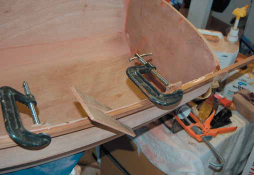
After the glue had hardened, I removed the temporary screws and bevelled the edges to fit the next panel. On the first couple of panels the curve helped clamp the edges together. But on the last panel, the curve was not so pronounced so it needed to be clamped while the glue hardened. As the pressure required was not great, I used some temporary clamps made simply of pieces of scrap plywood with a slot in them that just pushed into place.
Ply scrap protects from screw heads
Fitting panel
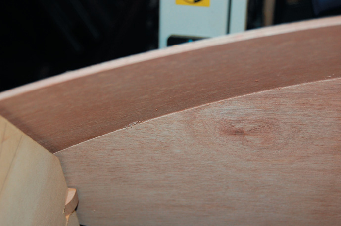
Close fit
Clamp lasts panel
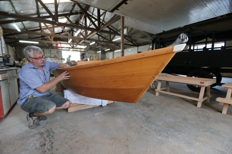
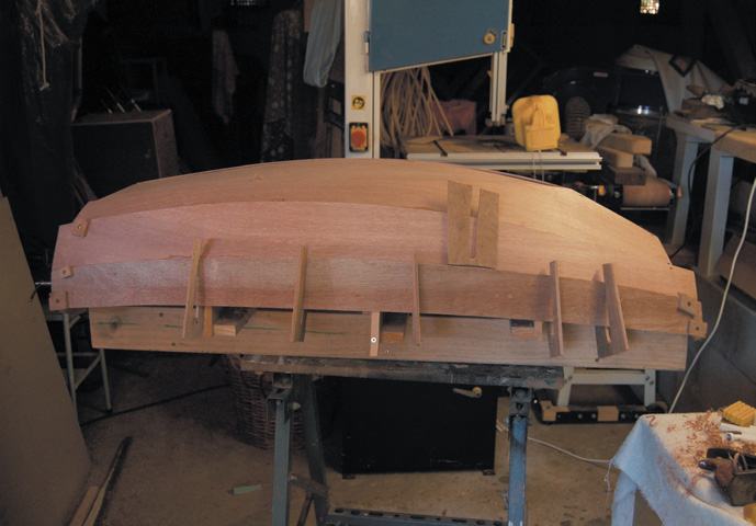
Hull test
When all the side panels were attached, the excess plywood was trimmed from the bow, stern and the bottom. I put filler in the panel overlaps to help strengthen them and make a nice smooth hull. It was then time to cross fingers and remove the hull from the jig to inspect my handiwork. I found the sides were quite flexible so stiffened them up by gluing a 10 mm-wide strip of timber along the top edge of the top plank on each side. (In nautical terms this is called the gunwale.)
This cedar strip was flexible enough to be bent easily around the curve of the hull without splintering or putting undue strain on the top plank. I planed the timber down until it bent nicely then screwed it into the bow and stern. When I was happy with the shape, I glued the strip in place using clamps to make sure it contacted all the way along. The strip then provided a handy guide for trimming the top plank to form a nice even curve from bow to stern.
I tidied up the glue runs I’d missed from the inside of the hull and faired in all the screw holes, edges and overlaps with filler then gave the whole inside a thorough sanding.
Next job was the knees that brace each corner. I made up cardboard templates then cut the shapes out of timber. As they were to be varnished, I chose an attractivegrained wood and put a big radius on the edge to minimise any chance of damaging the occupant. Fitting them was a fiddly business as they had to match a hull with both a curve and a taper. I glued and held them in place with tape until the glue set.
Trimming excess ply
Ceder strip gunwale stiffens shape
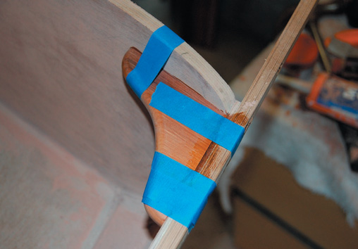
knees taped while glue sets
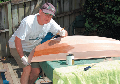
varnish first
Painting
Preparation is the key to all painting so I filled, faired and sanded with progressively finer sandpaper. I did the varnish first as it was much easier to remove an accidental paint drip from varnish than from bare wood when it has soaked in. I also checked that the paint I used was “baby safe.” As an extra precaution, I was careful to leave the paint as long as possible to make sure any solvents had dissipated.
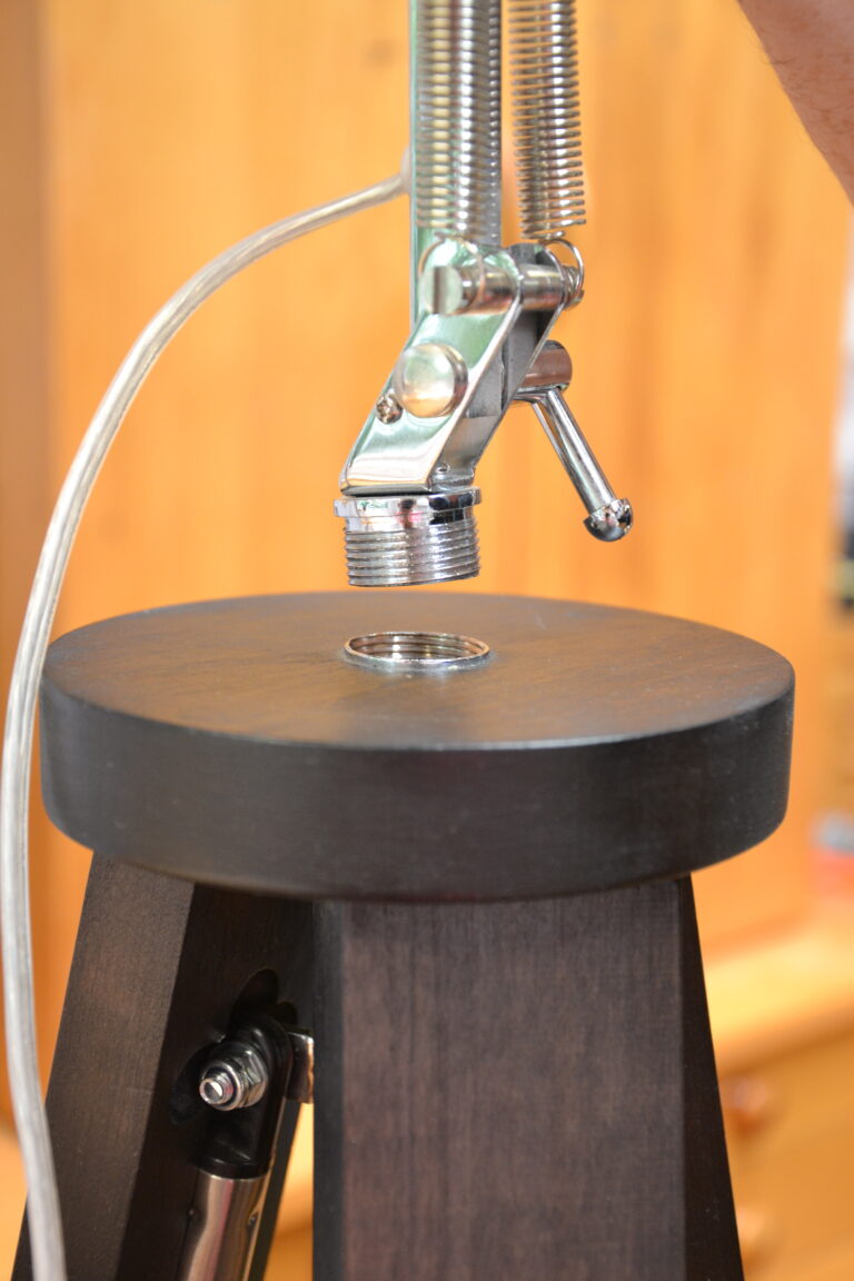
Stand
For a stand I went for one that could be adjusted for height and allowed the cradle to swing. The stand was made from solid two inch thick timber though I did think of laminating the uprights from strips. I drew out the shape of the uprights on the timber, top and tailing them to maximise the available width. The off-cut in the middle was used to make the feet, minimising timber wastage. The 200 mm x 25 mm cross-member was keyed and screwed into the uprights to make a solid frame. I then added blocks and cleats to hang the cradle from the brass eyes I had screwed to the hull. The stand with cradle was thoroughly tested with some heavy weights and crash-test soft toys before the crew went aboard when it performed perfectly.
The crew is rapidly growing up and although she has long since outgrown the cradle and graduated to a bed, she loves going out sailing with dad in the original full-sized dinghy whenever she gets the chance.
If I was going to build one again I would make it a bit smaller. A cradle boat can provide hours of pleasure in both building and for the crew. Made well, they can become family heirlooms, used for storing soft toys or put away ready for the next crew member.You could also adapt it as a rocking boat for bigger kids, add a mast and a sail with a skull and crossbones on it for a pirate play boat in the sandpit or strengthen it with fibreglass sheathing to create a play dinghy for kids up to 25 kg.
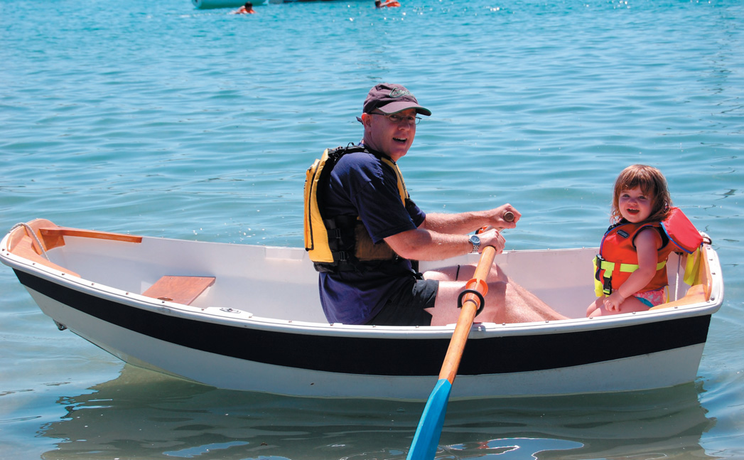
Father and daughter in full-size original