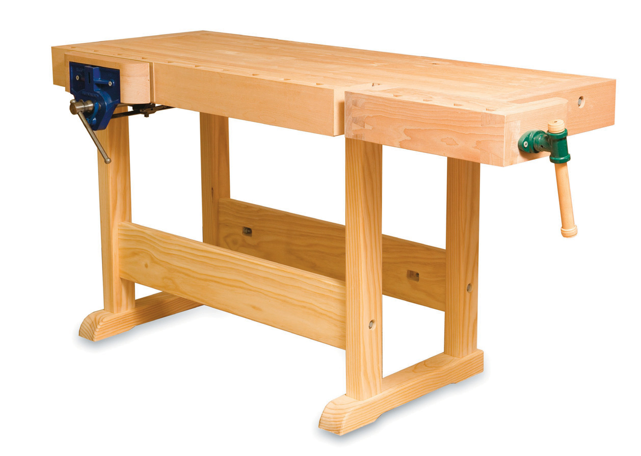
The second and final part of building a classic cabinetmaker’s bench
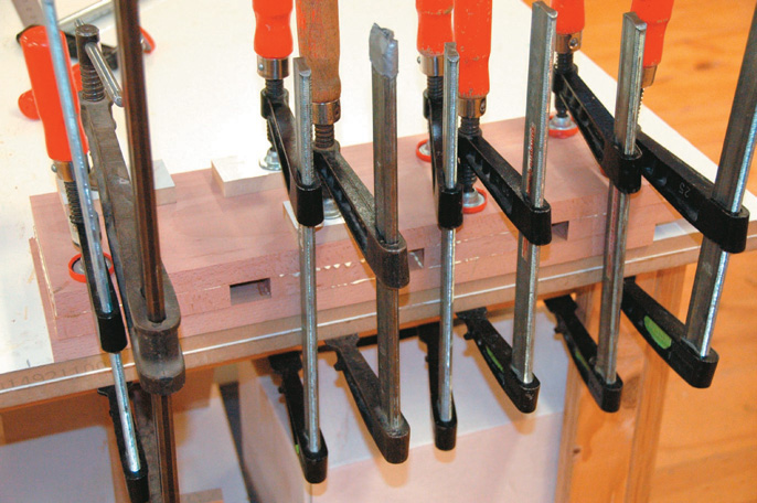
Gluing up
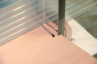
Trimming out dog run corners
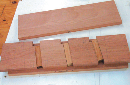
Dog run layout
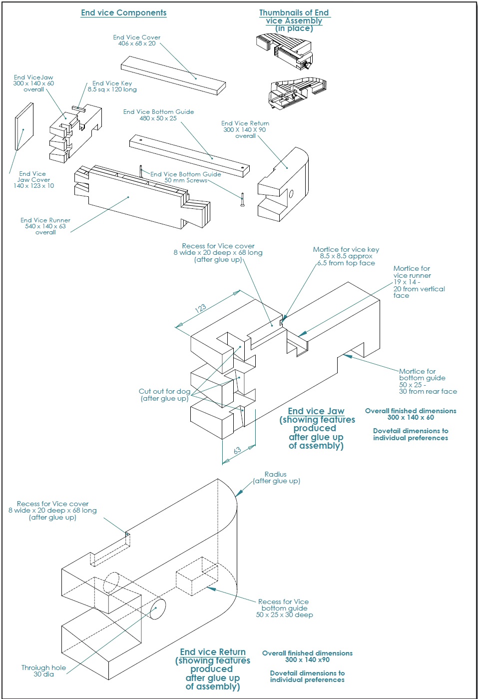
Right so now that your back from your warm sunny Pacific Island holiday—taken to recover from making the benchtop and frame—it’s time to get working on the vice. What we have on our hands is a beautiful little project of reasonable complexity that demands accuracy, uses both hand and machine-skills and is incredibly satisfying both when making it and using it. The concept behind the vice is a parallel box made up of four components that is driven along a series of guides and matching tongues and grooves by a single screw.
Dog run glue-up
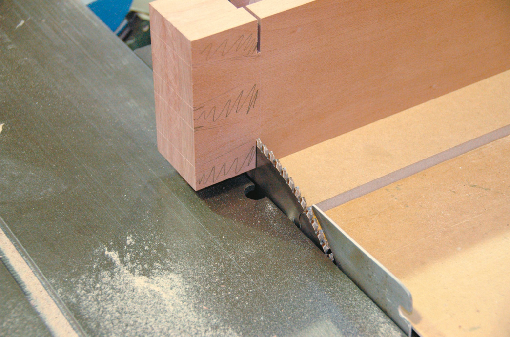
Using circular saw to cut shoulders of dovetails
Accurate
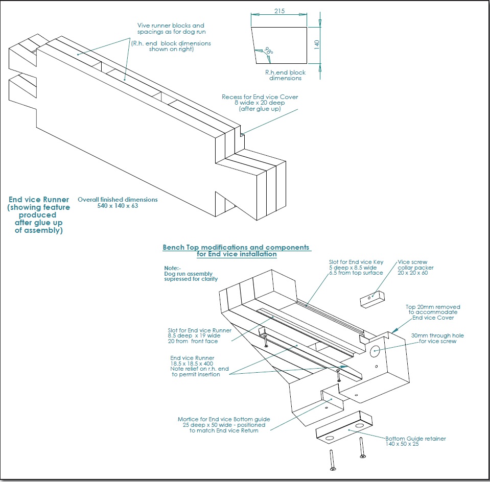
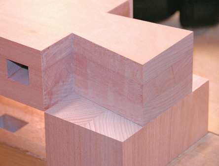
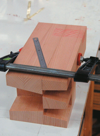
In order for the vice to function effectively, all stages of the construction must accurately keep the unit square and parallel. Familiarise yourself with the drawings in order to get a good understanding of how the parts will fit together. To begin the process we need to prepare the bench top; this means ensuring that the all the parts of the bench top are fitting together properly and the face which is to become the vice jaw is square. The bench end at the tail-vice end of the bench top becomes an integral part of the mechanism. This must be made flush with the bench top before we make any modifications to it. Three of the four components are of such size that they will be glued up from several pieces. These pieces should be sawn reasonably oversize, allowed to settle overnight ideally then re-machined to slightly oversize, glued up into the large blocks, allowed to settle again then carefully machined to final dimension size. Note the outside face of the vice is made in the same way that the dog run is made on the bench top (reversal of angle). Check the drawings for dimensions and lay out the elements carefully. The aim is to have the three pieces in final dimensions cut to length and square, ready to mark out the dovetailed corner joints.
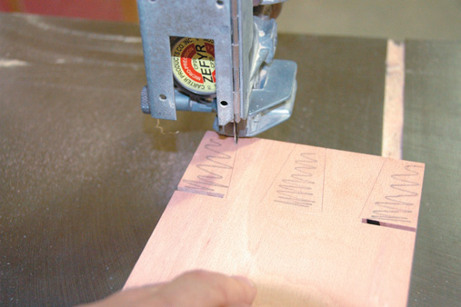
Bandsawing waste just outside the line
Cleaning up to line with broad chisel
Marking tail onto end of matching block, Use a sharp marketing knife
Cleaning out waste, Note paring block to ensure squareness
Dovetails start
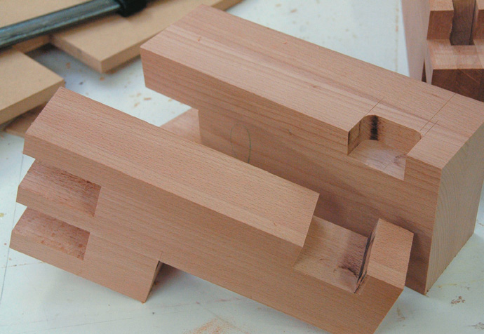
We start the construction by marking out the dovetails on to the vice front. This process of dovetailing is like any other. Check out the earlier article (“Dovetails—the benchmark” The Shed, Apr/May 2008) if you’re not familiar with the process. We start with the tails, cut them out to size then mark these on to the mating parts, set those out, remove the waste and fit the elements together. Because of the scale of these dovetails I chose to remove most of the waste with a band saw and circular saw, then used chisels to clean up to the knife line. These are possibly the biggest dovetails you will ever make—have fun. Once these three components fit well together, check again for square using diagonal measurements. Now we must fit one of the first slides—this goes into the bottom underside of the vice ends. Two rebates are routered through the components using a carefully made jig to ensure accurate location. A cutter with a parallel bearing on the shank is perfect for this job although it’ll be easier if yours is sharper than mine. Note how both parts are clamped together to ensure that the rebates finish up parallel to the outside face. Machine a matching piece of extremely hard wood for this slide—it should fit tightly and flush, but not so tight that you have to force it home.
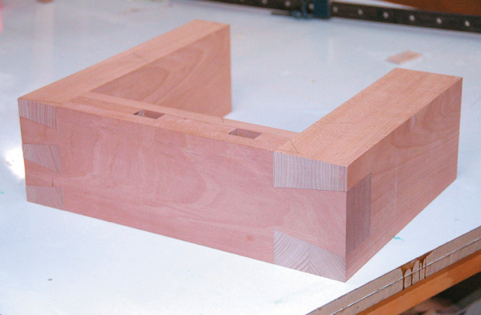
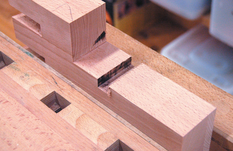
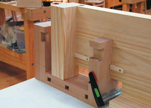
Dry-fitted joints. Note front dog hole has disappeared and will need to be re-cut after glue up
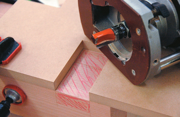
Template in place. Note bearing on shank of router bit
Marking out the rebate with both parts clamped together
Clean out corners with chisel. Note large rebate on opposite side of vice jaw
Large rebate
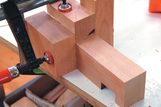
We now need to cut a large rebate into the component that becomes the vice jaw. The size of this rebate is defined by the existing thickness of your bench top and the depth from the outside of your dog run to the first element of the bench. The top edge of this rebate will slide along the underside of the bench. We must then cut a second small rebate across this newly created face (note how this is achieved in the photographs). This will provide us with a running groove for one of the guides. A matching groove in the bottom of the bench will provide a location for the guide itself. The guide should again be hardwood. Note the slight angle at one end to allow it to be slipped into place when finally assembling the vice and bench top. The last remaining element of the vice itself is the top plate. A rebate approx 20 mm deep is required for this to drop into and this is made using a rebate cutter in several cuts. Note the stops clamped into place to ensure the cutter can only cut where we want it to.
Extra blocks clamped in place to steady router while running groove
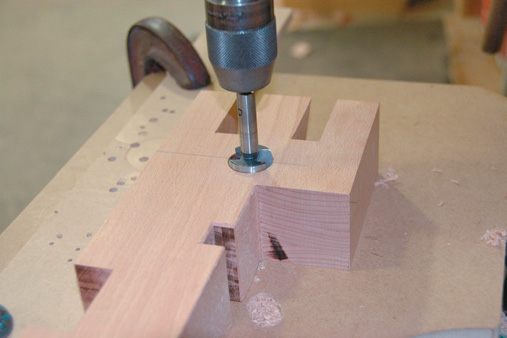
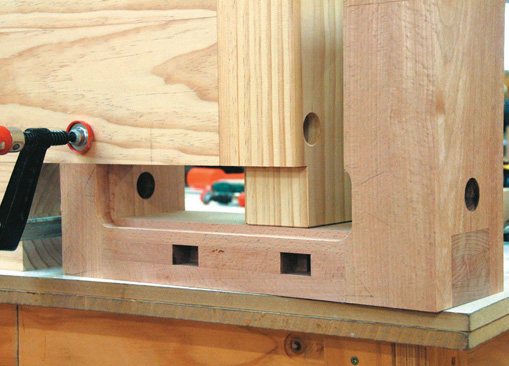
Bench end
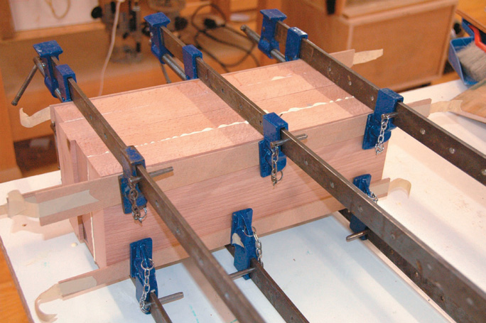
Now it’s time to sort out the bench end, cutting this to length so that it extends beyond the bench itself as far as required to touch the inside face of the vice front. We then cut a rebate out of the top of this bench end equivalent to the thickness of the top plate. You can see when the top plate is fixed in place the underside will slide over the top of the new rebate. Now drill holes for the screw. The one through the vice should be 2-3 mm greater in diameter than the screw itself. Check the length of your screw against the dry assembled vice and drill into the back of the vice jaw if necessary to allow the screw to go right home. Put the vice in place on the bench and match the screw hole in the vice itself to the bench end. Drill through the bench end making the same diameter hole. So it’s now glue-up time. First do a final dry-clamp to figure out the most effective location of the clamps and ensure that everything goes home square and parallel. Then put it all together with glue and clean up.
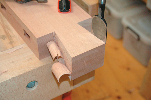
Groove
A groove in the edge of the bench is run next. This matches a groove we run in the vice into which we put a hardwood tongue. The tongue will eventually be glued in place and it will slide backwards and forwards along the matching groove in the bench edge. Using a slot cutter in a router and cutting both grooves on the same router setting will ensure they match. Once again, check drawings for accurate locations. We can now place the vice into its location. The last thing we need to do is match the grooves in the undersides of the vice face and back with a new slot cut into the underside of the bench end. Use the original template we made earlier to ensure all three rebates are the same dimension and in perfect alignment. Our major vice slide will travel backwards and forwards through this groove and will be captured by screwing a locating piece of wood over the top. This slide can now be screwed in place. The nut for the vice screw should also be screwed in place inside the face of the bench end. Note you will probably have to fit a small packer in place to allow the nut to fully seat. Then the final slide should be slipped into position underneath the bench. This should firmly lock the vice into place. Chop through the bench dog hole that was filled when the dovetails fitted together, clean up the vice, make a round corner on the outside back edge, flush the surfaces off, insert the screw, fix the flange into place and try winding the vice backwards and forwards. If all has gone well the vice should run with some friction but stay perfectly parallel as it withdraws. Gluing a sacrificial face on to the jaw of the vice will protect your careful construction and allow you to true the vice jaws each time they become worn.Your bench should now be looking superb. Allow yourself a few minutes to humbly walk the neighbourhood accepting the resultant praise and accolades. Then return and make the spring loaded bench dogs that make it such a wonderfully flexible tool and a nice handle. Well I hope you’ve enjoyed this as much as I have. Special thanks to Ryo, Mia and Lachie and everyone in the Centre for Fine Woodworking shop who tolerated my repeated dis-assembly of their vices—usually at critical times—to try to remember how it was done. John Towse of T Tech Design has been wonderful with his patient and skilful working up of the drawings and Dan Allen of Daniel Allen Photography provided his usual fantastic level of support. Cheers. It is worth noting that a kit made of three metal plates with matching grooves can now be purchased to enable the fixing of a tail vice onto a cabinet making bench. We usethese also at the Centre but generally find that they still require a reasonable amount of fitting and tuning to ensure their effectiveness and the construction of the vice itself is different—drawings for this type of vice are provided with the kit.
Groove run
Drilling for vice screw
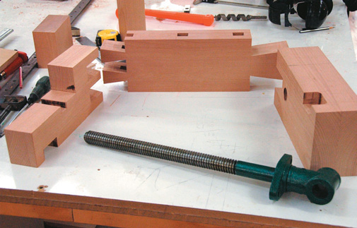
Dismantled vice

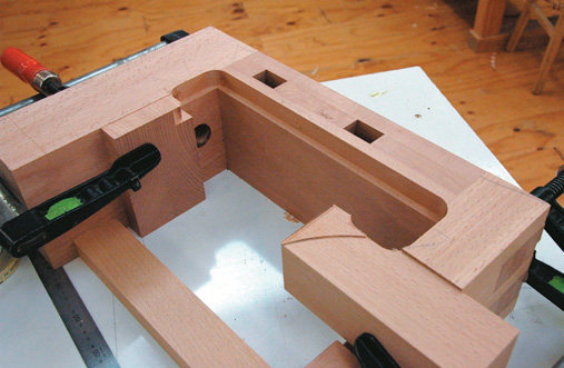
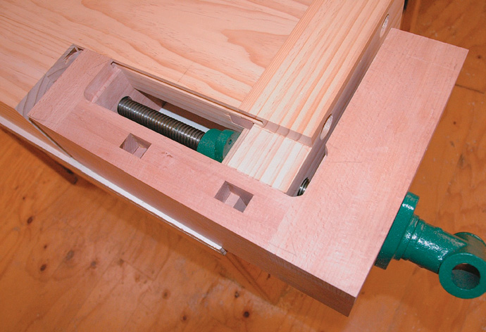
Dry assembly with vice guide in place
Rebate for vice cover run. Note blocks clamped on to prevent over-run cutter
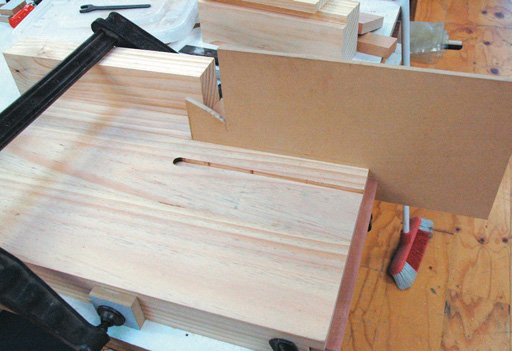
Improvised fence for router when running groove in underside of bench
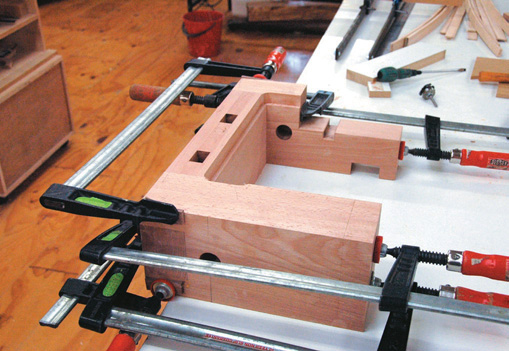
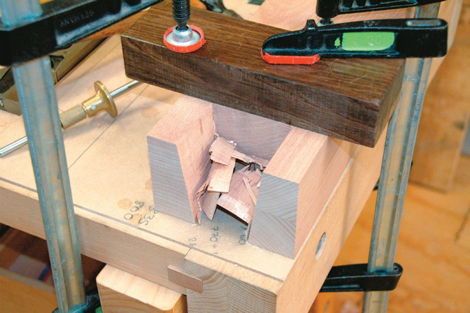
Glue up
Vice in place on bench allows locaton of matching rebate in bench-end
Checking overall vice-to-bench fit
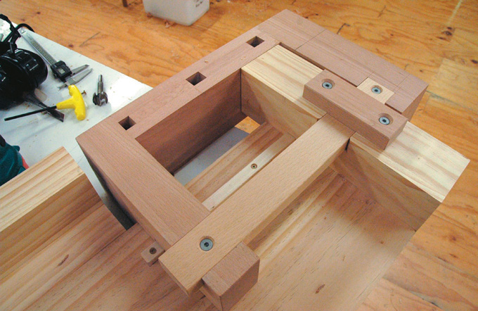
Main vice guide screwed in place and captured with retainer screwed in place
Final location and fit. Note final pair of grooves now run in and spline ( not visable) glued into vice jaw. Time to fit vice cover