HOW TO MAKE YOUR OWN HYDROPONICS NUTRIENT METER.
Hydroponics is all about growing without soil. In many ways this simplifies the lot of the gardener, but it gives them added responsibility for providing plants with the right level of nutrients. As water with nutrients tastes, feels and looks much the same as plain water, a testing instrument called an “EC meter” or “CF meter” is used. The hand-held ones tend to look a lot like a truncheon with party lights down the side and indicate the nutrient level in EC or CF units (.1 EC unit = 10 CF units). The way they work is a bit complex, but we’ve figured out how to replace a lot of the esoteric circuitry with an ordinary Arduino. Not only can you build a CF meter cheaply, but you can also easily modify it for a garden automation project. All the meter does is measure the resistance of the water. Lots of nutrients means a lower resistance. If you just use an ordinary resistance meter, the current passed through the liquid changes the nutrient’s chemistry and your reading goes inaccurate very quickly. So CF meters measure the conductivity in short pulses, swapping direction each time they make a measurement to reverse the chemistry.
The process
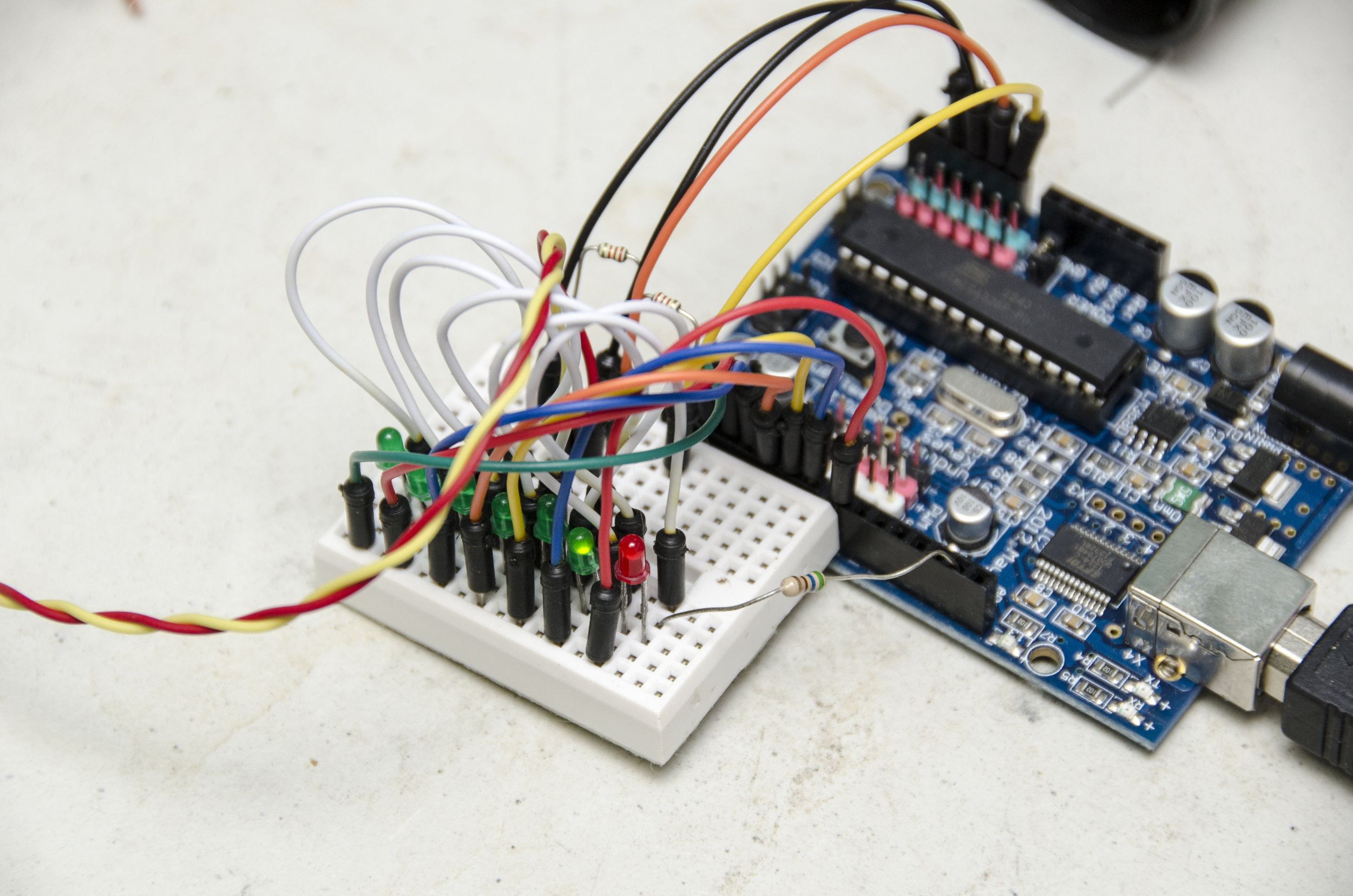
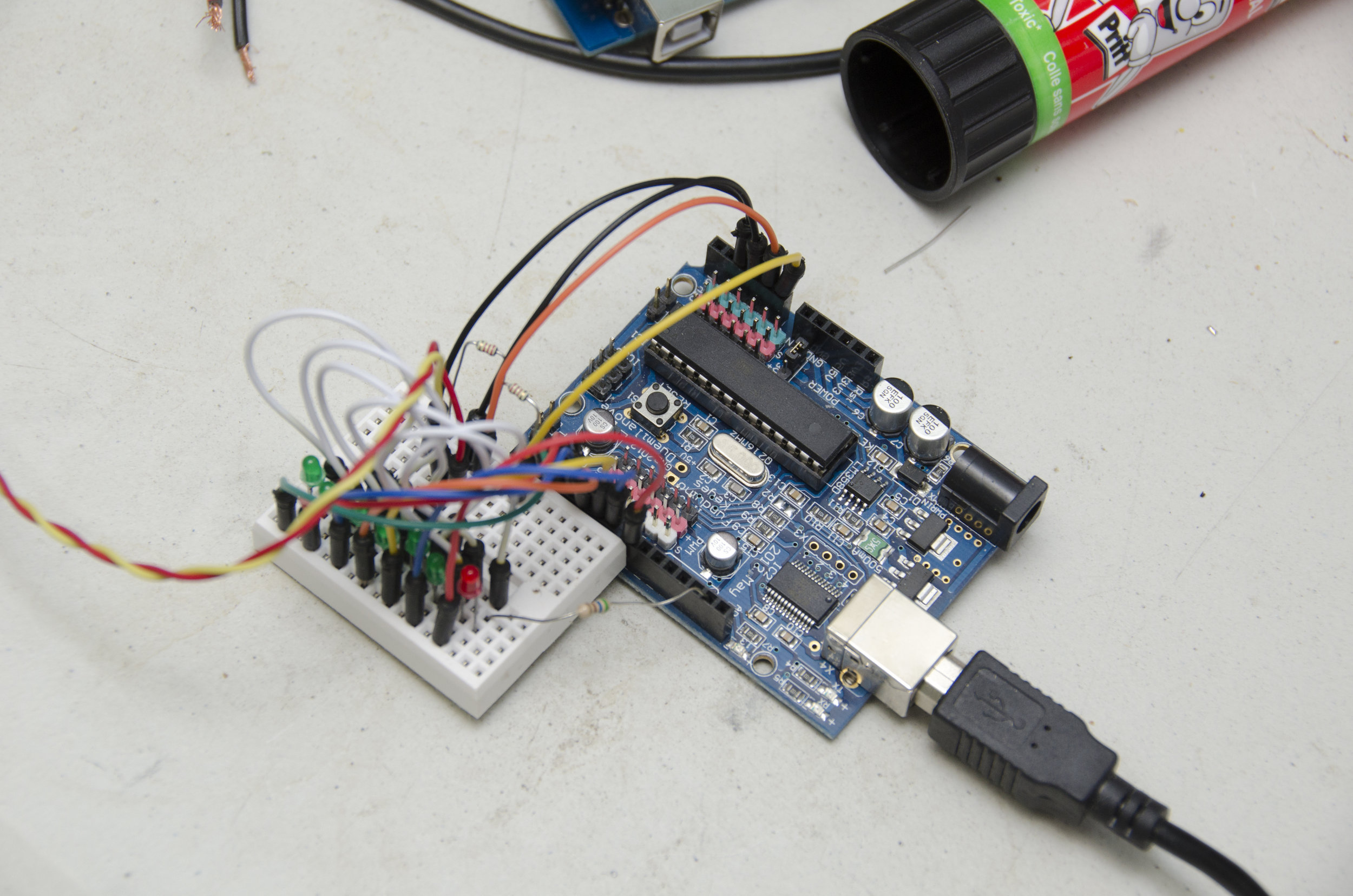
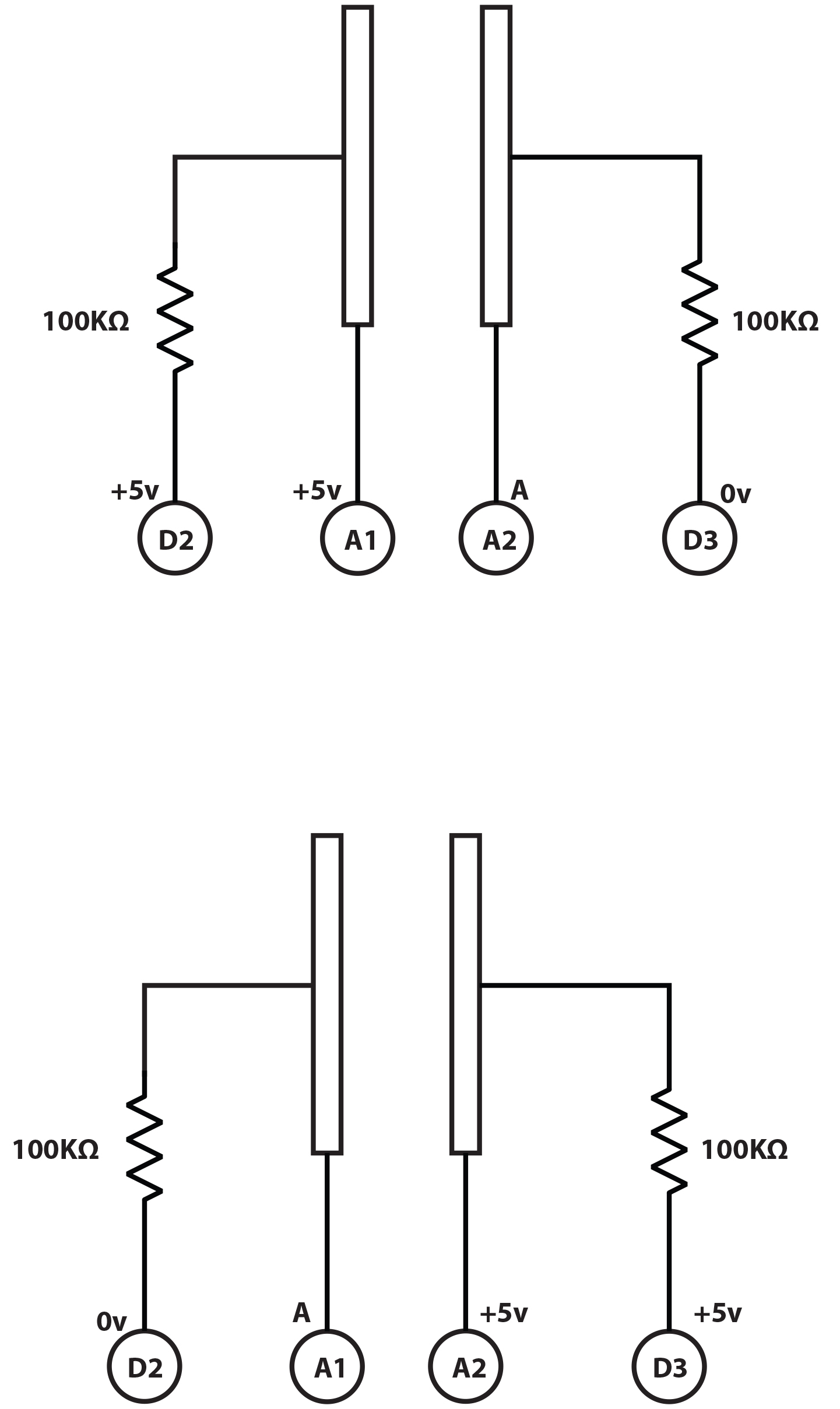
Make a rust-proof probe by carefully cutting the carbon rod from the centre of an AA zinc/carbon battery. Clean it, clean everything else you got the mess on, then boil the rod in water for a few minutes to get the last of the battery compounds out of it. Break it into two pieces, notch the ends with a file, then wrap and tightly twist a bare copper wire into each notch. Thoroughly embed the whole thing in your favourite waterproof plastic (eg, Sugru, polymorph or silicone) leaving just a couple of millimetres of each rod sticking out about 10 mm apart. No nutrient solution must get in or it will corrode the copper. That’s your sensor and you can hook it up to the A1 and A2 Arduino pins. A slightly better idea is to wire things up to a socket that can be detached easily from the Arduino—this project isn’t complicated enough to require a circuit board. Instead of the impressive collection of op-amps and comparator chips in a commercial meter, we’re going to use a couple of resistors and an Arduino to do the measuring. Arduino has pins to measure voltage and these can also be used to output a voltage. This circuit simply alternates two pins between measuring and volting. Add a couple of resistors as per the diagram so we can compare the voltage dropped across the probe with the voltage dropped across a known resistance. The device built here uses two 2.2K Ohms resistors (red, red, red bands) but you use a value of roughly one tenth of the resistance you measure when you put your probe in: a very weak—0.1CF—test solution. So if your probe measures the solution at 35K Ohms, use a 3.3K Ohm resistor and so forth. Put one across A0 and A1 and the other across A2 and A3. You might feel happier building it on a breadboard first.
Meter code
At this point you can use the Arduino development kit (“IDE”) from http:// arduino.cc to load in the CF meter’s code. Instructions to do this for your Arduino and computer types can be found there. Under [Tools] is the “Serial Monitor” and this will show you the readings that the meter is reporting. The first number is the raw reading from the sensor, the second number (if present) is the CF value. Calibration is a bit tricky and, unless you have EC buffer solutions handy, you’ll want to borrow a real EC meter. We use CF units rather than EC units because they’re largish integers to which both the Arduino and humans find easier to relate. Dunk the sensor in the very weak 0.1CF solution to get the “baseValue”—make sure you completely cover the exposed probe tips and edit it in to the line saying: const int baseValue=340; // Value of weak 0.1CF solution The “cfTable[]” code below that line consists of a series of [sensor reading, CF reading] pairs. The first pair should be your baseValue and zero. To get a few other pairs, ideally you would mix up slightly salty water, measure its CF value with a borrowed EC meter and then test it with your probe. If you expand or reduce the table do remember to alter the TABLE_ENTRIES count. If you can’t borrow a real meter, 1 gram of table salt thoroughly dissolved in 500 ml of deionised or distilled water will have a CF of about 40. Take half of that, dilute it back to 500 ml again and it’ll have a CF of 20. Repeat for CFs of 10 and 5. Finally, dilute 5:1 to get a CF of 1 and use these solutions to calibrate the probe. Once you have entered the values into the code, save it and upload it to the Arduino again. Now when you dunk in the probe, you should see the CF reported in the Serial Monitor. If you’re using this to make an automation system and know what you’re doing, you can probably use the project pretty much as-is. The important thing is to remember to call the neutral () routine as soon as the measurements are done to turn off the sensor and prevent chemistry happening. It’s all open-source software under the GPL so feel free to share and enjoy.
Stand alone
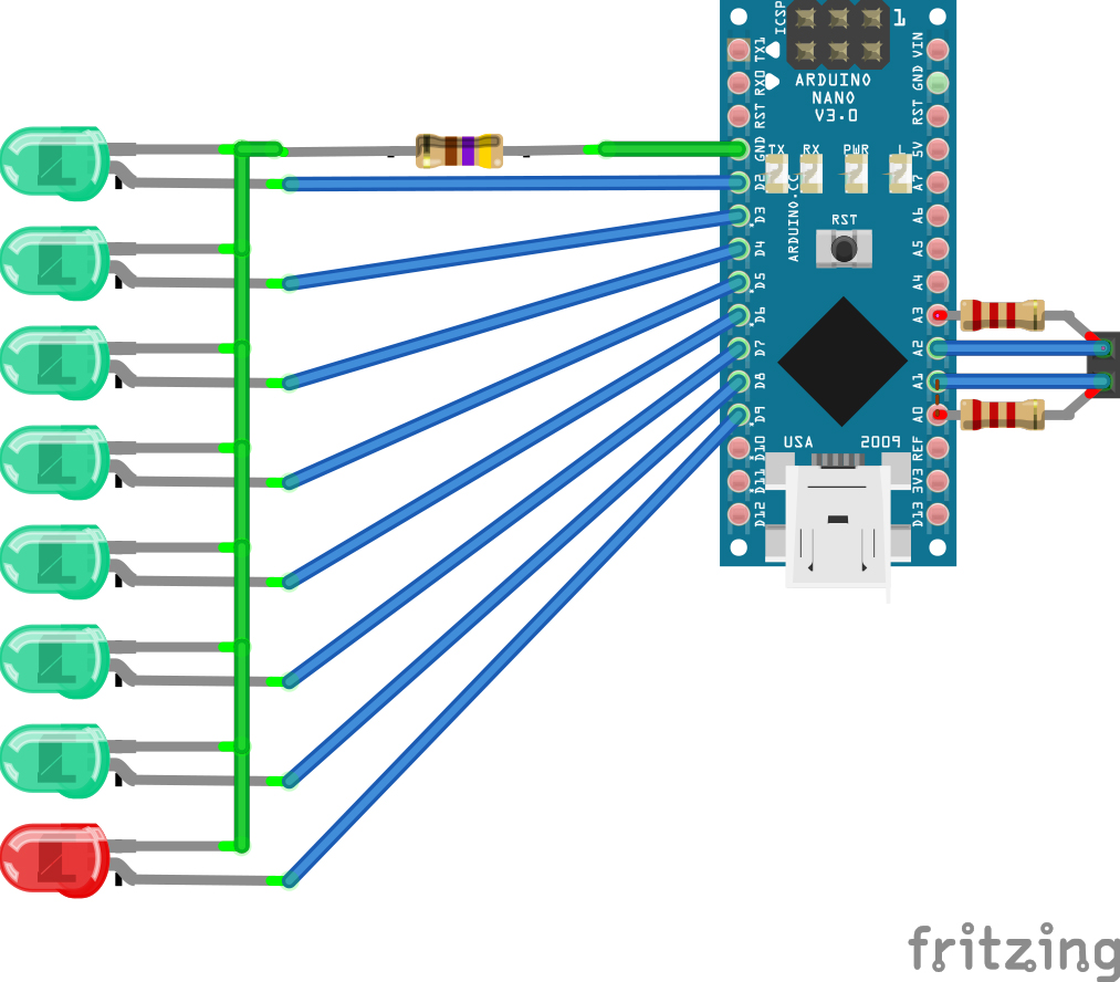
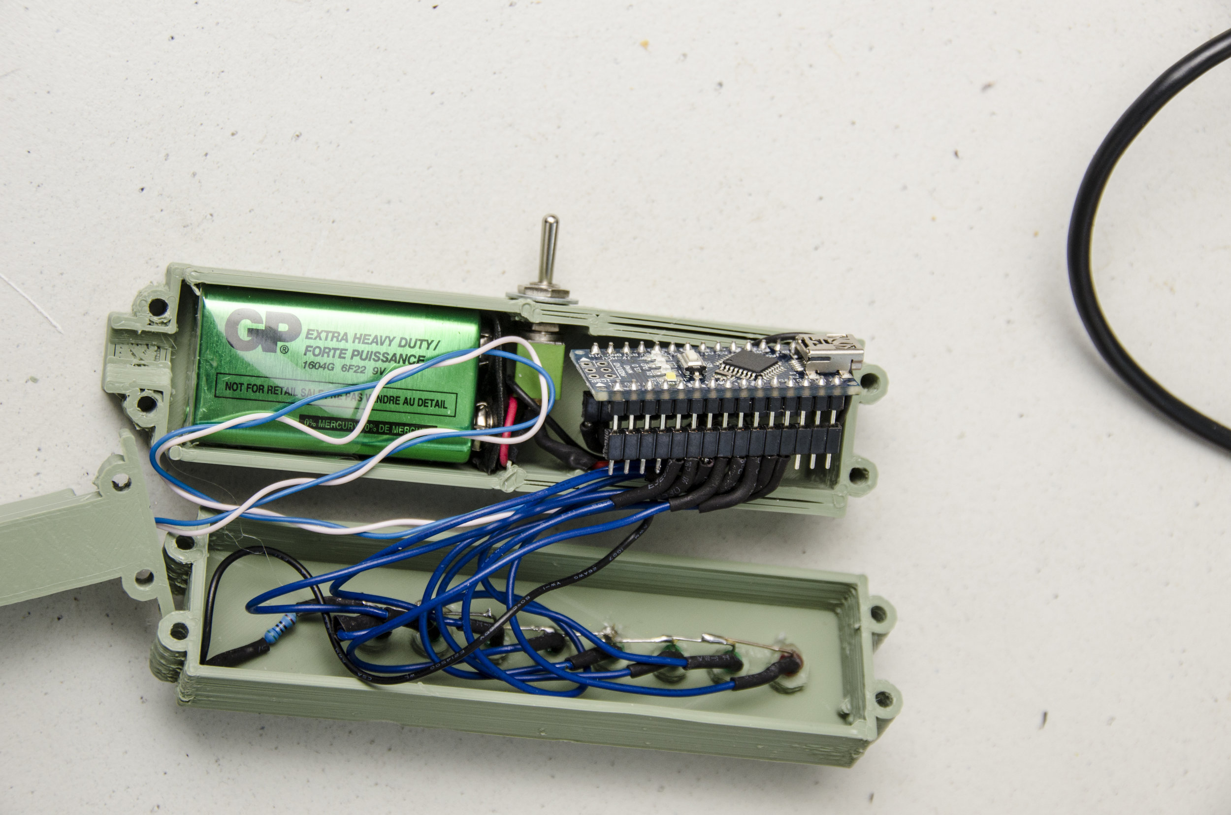
If you want to make a stand-alone meter out of it, you can add a line of LEDs to the Arduino. The “pinTable[]” array contains a list of the pins you have LEDs on, put in the order in which you want them to light up. You can add spare analogue pins if you wish to make the line of LEDs even longer, just update the LED_TABLE_ ENTRIES number accordingly. The LEDs will strobe until the meter measures something and then light the appropriate LED. A value corresponding to a point part-way between two LEDs causes them both to blink. Because we’re only lighting one LED at a time, we can get away with just one resistor to control the drive current. So all the LED cathode leads (usually lead on the chunkiest half of the metalwork inside an LED) are wired together, then to GND. The anode LED leads go to your chosen Arduino pins. Diamond age ad I powered mine from a USB emergency phone charger, but you can use a 9V battery connected to GND and Vin instead. Some form of switch is probably in order and then your stand-alone meter is complete. If you can get to a 3D printer, a printable case for the LED-bespangled Arduino Nano version is here: http:// www.thingiverse.com/thing:704520 and the software can be downloaded from GitHub here: http://github.com/ VikOlliver/CF_Blinkenlights (look for “Download ZIP”). CF changes by temperature, but by less than 1 unit for 10°C, so for most practical purposes we can ignore the temperature, insert the probe, and measure away— unless it freezes, of course.