By Terry King
In this article, we show how an arduino microprocessor is complex enough to exercise variable control, not just the expected computer approach which is that something is working, or it is not. Digital devices have only two states: on or off. An analogue device on the other hand can have a near infinite range of states. Think of a light; it can be dimmed or brightened by adjusting the current. Arduino can provide an analogue output. It’s called analogueWrite( )and it is used to control the brightness of a LED, the volume of an audio output or the speed of a motor. It does this with a technique called Pulse Width Modulation (PWM). PWM is available on pins: 3, 5, 6, 9, 10, 11.
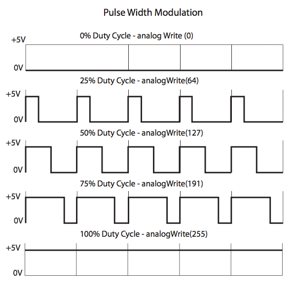
In the first article Arduino 101 Part 1 we made a LED work so fast that its blinking ceased and it appeared became a constant light source. We did so by changing the delay between the pulses. This is what PWM does. The arduino outputs a square wave, a simple on and off signal, which flips between OV (LOW)and 5V (HIGH). Varying the duration of the (HIGH) signal versus the (LOW) will change the apparent brightness of the LED. The pulses can be varied in discrete steps between 0 and 255 with 0 being Low and 255 High. At a value of 127, the pulse will be HIGH for 50 percent of the time and LOW for 50 percent.
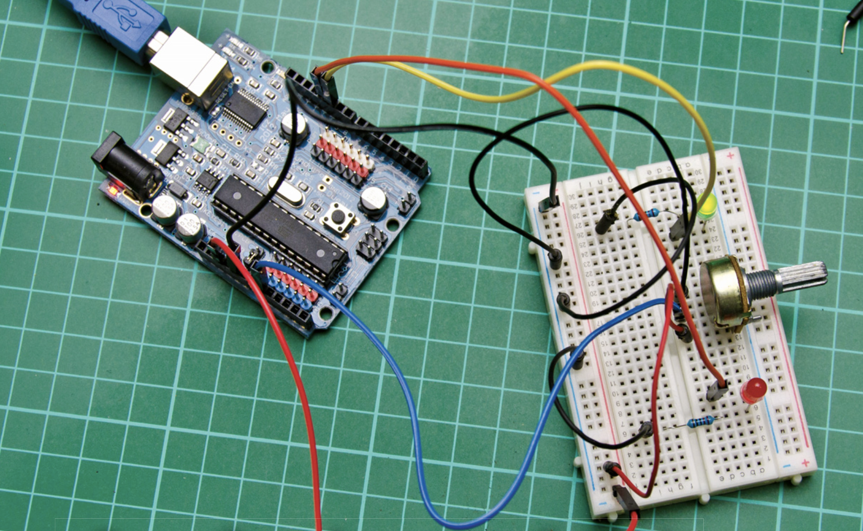
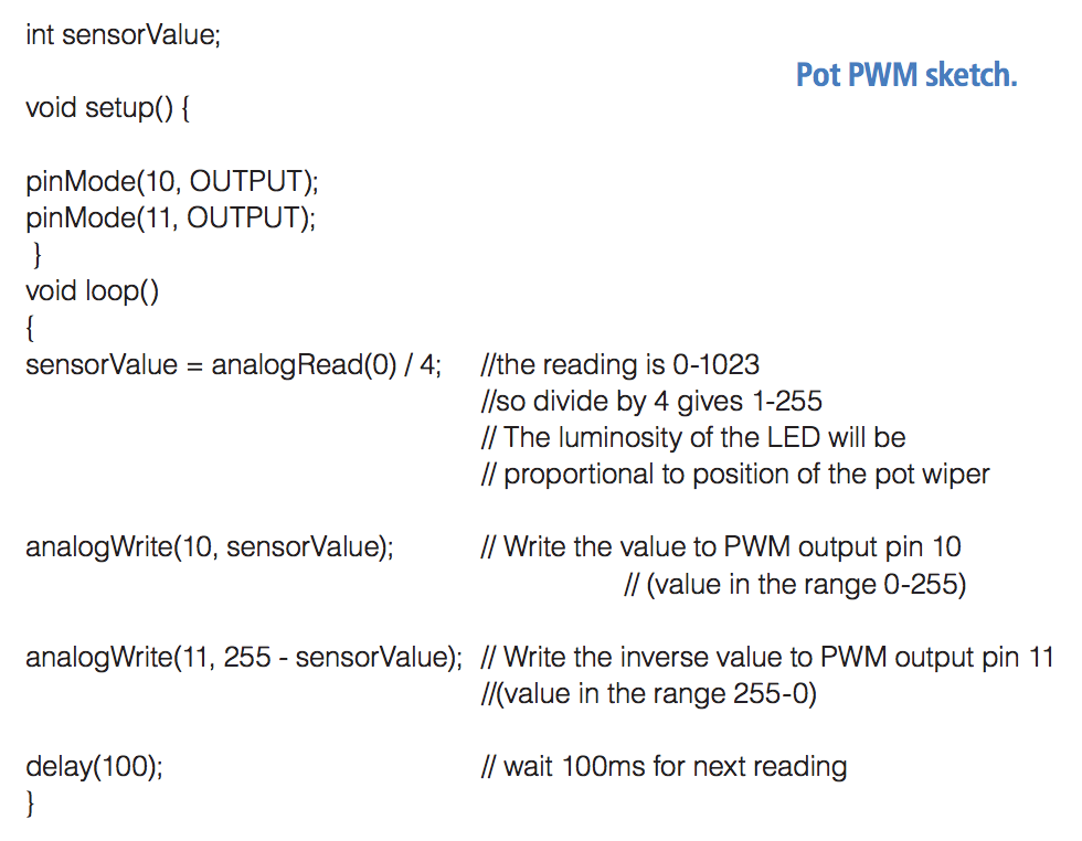
The set up for the potentiometer PMW sketch
The duty cycle of the pulse is 50 percent so the LED is receiving an on signal for only 50 percent of the time; to the eye it appears to be dimmer. At a setting of 64 (25 percent of the 255 maximum) the pulse would be on for only 25 percent and low for 75 percent, a duty cycle of 25 percent and the LED would appear only 25 percent as bright.
Having to program in the brightness will have its uses but if we want more immediate control using PWM we can use an analogue device like a potentiometer (pot). To do this we will have to set up the arduino to read the analogue values of the pot (as we did for the servo example in Part 2, The Shed Oct/Nov 2012) and set these values as PWM values. In this case we will use two LEDs. One will become brighter as the other decreases.
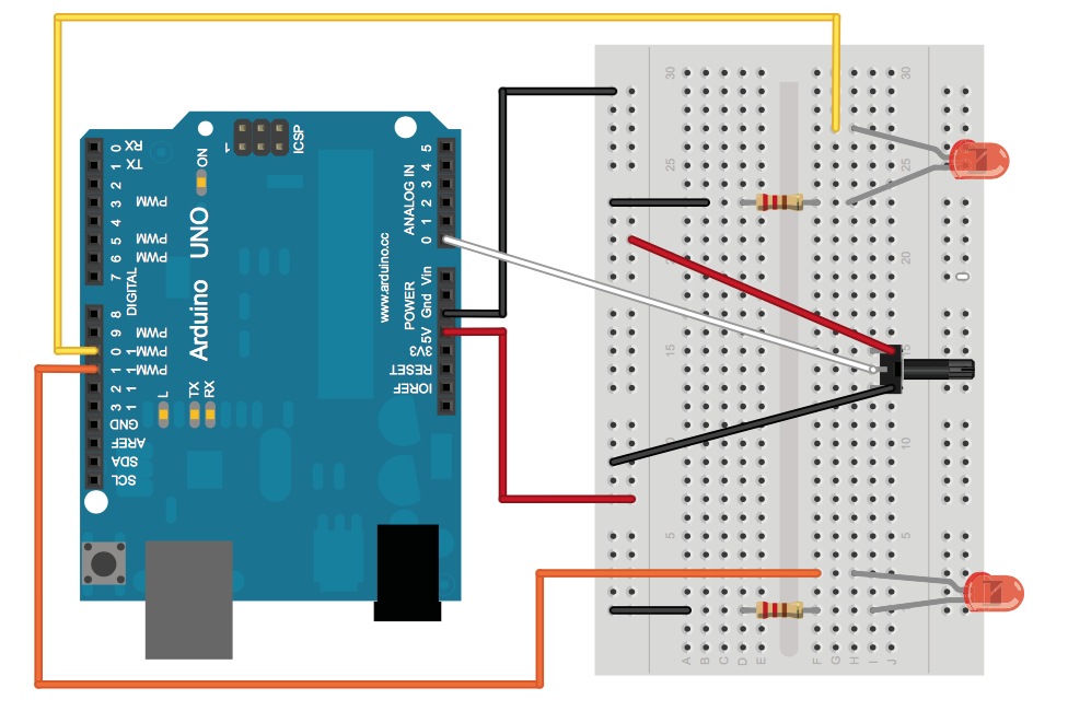
Wiring layout for the pot PWM sketch. This was made with Fritzing software which can be downloaded at www.fritzing.org
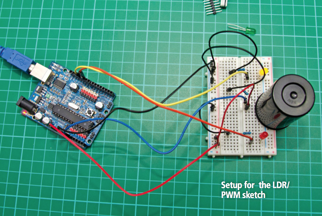
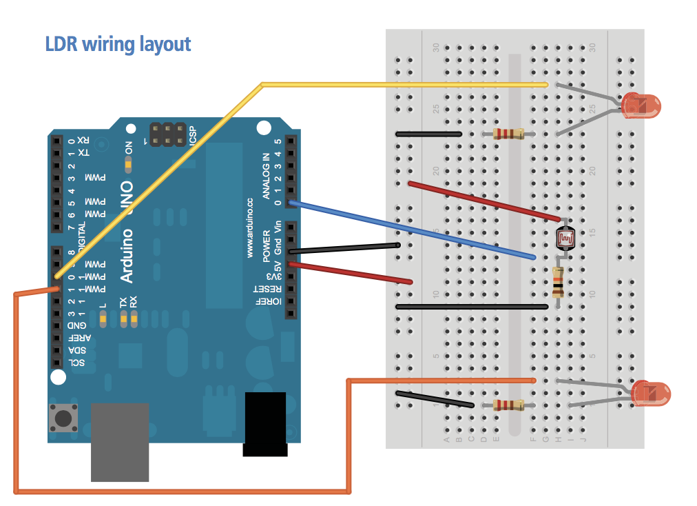
Now we will add another level of complexity by using a sensor to control the output. This time we will use an LDR or Light Dependent Resistor. This is a resistor that changes its resistance in response to the presence of light. The LDR has a high resistance until it detects light. However we can configure it much the same as the pot to deliver a value to light a LED. This has a number of uses: turning on the lights as darkness approaches; detecting something passing across a sensor (think of the light-based doorway sentries).
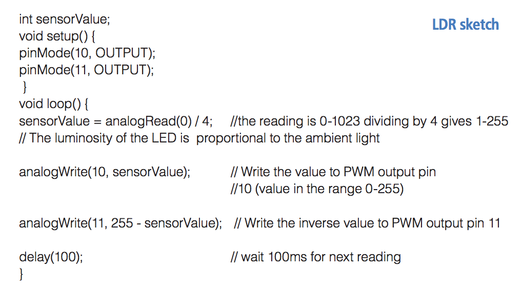
The values the LDR delivers are not exactly proportional to the analogueWrite() output. So we have to calibrate the output. Set up the LDR on the breadboard as shown and run the following sketch. Use something to block the light to the LDR and see the LED alter in brightness. A black film canister works well (if you can still find one).
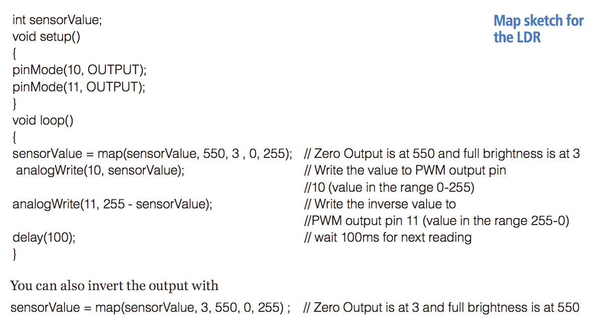
The LDR doesn’t always work over the full possible range of responses and in fact may operate over only a limited range. So to maximise the range we need to map the output. Map is a common function in arduino programming wherever analogue devices are used. It determines the input parameters (0-1023) and aligns these to the output values (0-255). Usually the sensor will operate over a much smaller range so to ensure proportionality we need to map its range of responses and match these to the digital output.
Serial Communication
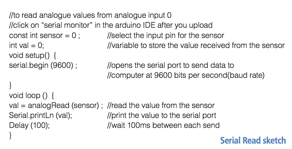
It can be useful to read the values directly. The arduino is powered and programmed via the USB port and this port is a two-way communications device. Through it we can read the input of devices connected to the arduino, too. This is called serial communication. To view the values read from the LDR, use the following sketch. After you have uploaded the sketch click on the monitor button in the top right-hand corner of the IDE screen or select the “serial monitor” from the Tools menu in the Arduino IDE. Read off the values with the LDR fully exposed and fully covered.
Mapping results
Now we can map these maximum and minimum values to the arduino to see if there is any improvement in the accuracy. We got a reading of 3 when dark to 550 for full light, so map these figures using the MAP sketch. There is another way to set and calibrate the analogue readings directly. It is in the example sketches of the Arduino IDE under Analogue/Calibration. This sketch will allow the sensor to calibrate in the first five seconds after starting and map the values it receives to the analogue output. It does effectively what we just did with the serial interface and then carries out the PWM program using those values.
Project
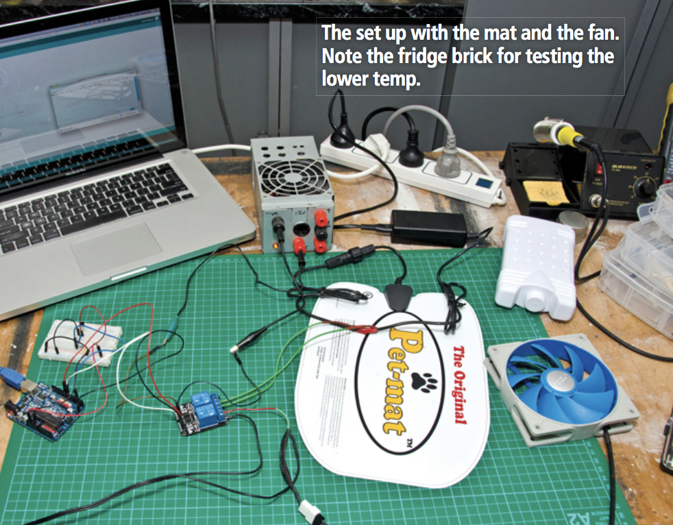
It’s time we started to implement all this in something more practical. Here we will use some of the above to create a device that will activate a heater or a fan. It’s basically a thermostat and it could be used to control a heater in a fish tank or temperature and humidity in a glasshouse or even controlling the temperature of your home brew.
This one will be used to provide climate control for a kennel, which actually houses a cat banished to the outdoors for anti-social habits. We will make use of two more items from The Shed Arduino Kit—the temperature sensor and the opto-isolated 2 channel relay.
A relay is a means of switching high- powered devices without actually having to connect the microcontroller directly to the device. The opto-isolator means there is no direct electrical connection between the arduino and the load being switched.
The isolator works with an infrared LED and photosensitive transistor in a tiny package. The opto-isolated relays are rated to work with 240 Volt mains power. We urge you use extreme caution working with mains-powered devices.
Ideally don’t mess with it unless you really know what you’re doing and ideally always use an RCD between the device and mains. In our case, we will set the relay to switch a 12V fan salvaged from a computer and for the heater a 12V powered carbon- fibre heat pad. You can substitute LEDs or even 12-volt lights to test that the device is working.
2 Channel Relay
The relay requires its own 5V power source. The arduino cannot reliably supply sufficient current to switch the relays (actually it can just but it is safer to use a separate supply). So you will need to remove the jumper between JD-VCC and VCC on the right and connect the relay power supply here. You can use a 5V supply from a phone charger as long as it has at least 1amp capacity.
The digital inputs from arduino are active LOW. The relay operates and the LED lights when the input is set LOW.
You will still need to connect VCC from the arduino and the signal wires to the relay board. There is no need to connect the ground wire from arduino as the board can use the common ground from the power supply.
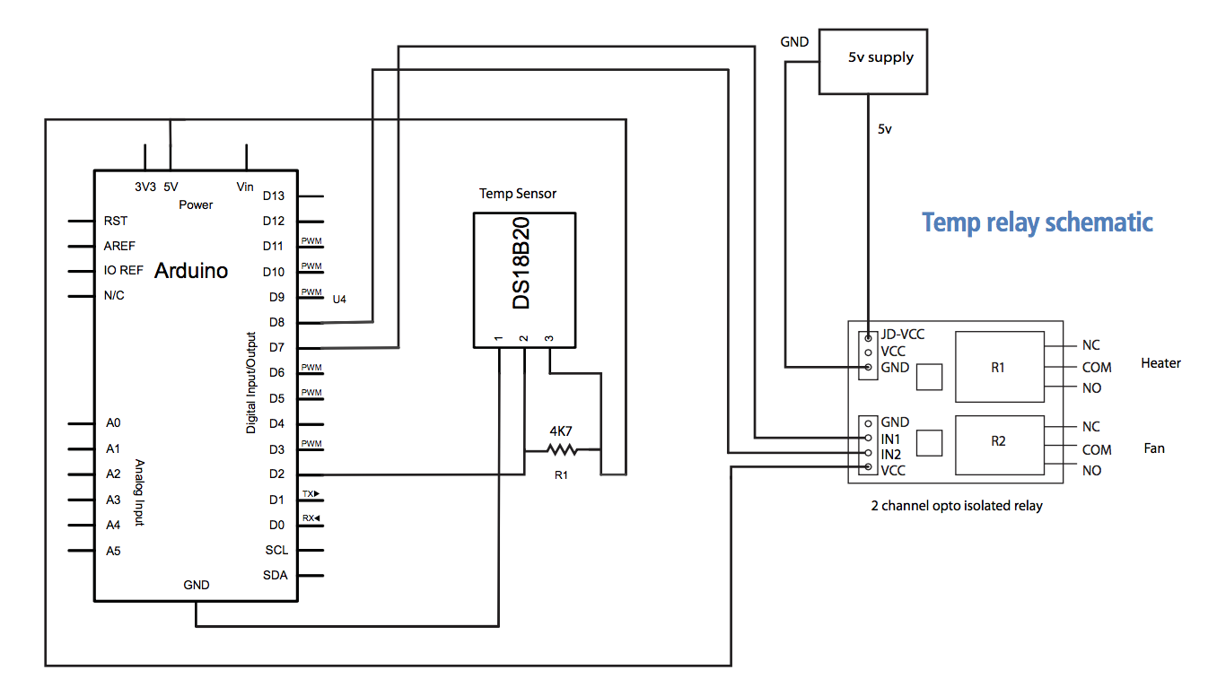
Temp control of Relays
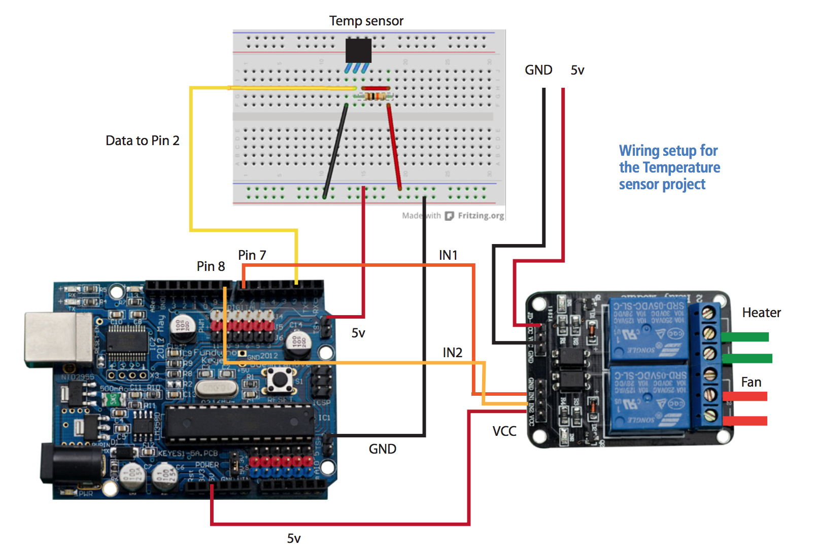
The Maxim (formerly Dallas) One Wire range are clever beasts that are able to pass power and data over the same wire. They actually need two wires (Pwr/Data and GND), but for this example we will use all three. Connect the DS18B20 to + 5V and GND. The Data goes to Pin 2 of the Arduino. Data sheets on the device can be found at http://datasheets.maximintegrated. com/en/ds/DS18B20.pdf or http:// www.arduino.cc/playground/Learning/ OneWire.
The later is an excellent learning site too. Fita4K7Ω(oruse2x10kinparallel) pull-up resistor between +5V and Data pin (Pin 2). Relay Outputs use Pin 7 and Pin 8 of the arduino. There is no particular reason for this except they aren’t PWM pins. The sketch identifies it can reach a DS18B20 chip, and then reads the DS18B20 every second (it takes 750mS for a full reading to be available).
If the temperature is below 14°C, then it turns on Pin 7 which operates the heater relay. If the temperature is above 29°C then it turns on Pin 8 which operates the Fan relay. We can flash pin 13 (LED) to show it running and have it ON when one or other relay is on. We will use two settings for each temperature i.e.LowTempOn (14°C) and LowTempOff (24°C), HighTempOn (29°C) and HighTempOff (25°C) to stop the relay chattering. You can set the values wherever you wish however.
Sketch
Because of its length and complexity we have loaded the sketch to the dedicated arduino page on the The Shed magazine website (www.theshedmag.co.nz) along with the OneWire library you will need. Before you load the sketch you will need to load the OneWire library. To do this, find the arduino folder for PC. It will be MyDocuments/Arduino/Libraries and for Mac it will be Documents/Arduino/ Libraries. If you haven’t got a folder called Libraries make one and download the OneWire.h file from the arduino folder on The Shed magazine site and install it here. Do this before you start up Arduino IDE. Upon start up, arduino will find the Libraries file and install it under the Sketch/Import library menu. You should find it under the Contributed menu. Now when you load the sketch it will find and retrieve the OneWire library protocol to identify the device.
Setting Up
The relay requires one power lead be run through the relay. Relays have three connections NO, COM and NC. The NC (normally closed) is set to the COM. Connect +12v power lead to the COM (Active for AC) then connect the NO to the Fan (or Heater).
Once everything is set up, run the sketch and turn on the serial monitor. You will see the temperature begin to scroll. You can test the relays by holding the temperature sensor between your fingers and watch the temperature rise. You should get to 30°C this way so it should easily trigger the fan. I found I could use a chilly bin refrigerant brick to get the temperature low enough for the heater unit. Removing the arduino from the computer and powering it with yet another 5V wall wart (never throw out a wall wart) kept the process going all night. Now it just remains to package it properly and test it on the resident.