Calculate gears, sprockets and pulleys
By Bob Hulme
As sheddies, we are known to cobble together machines from whatever we have at hand. More often than not these items are less than ideal and a motor of some sort may run at a different speed to what we need. If we are looking to make a spindle moulder, belt sander, garden chipper, wind generator, compressor or similar item then it is likely that some sort of gearing will be necessary to give the right RPM at the business end.
Calculating the sizes of gears, sprockets or pulleys is a relatively simple exercise. Below is an easy reference to save having to work it out from basic principles each time.
Gears and sprockets
The easiest calculation is with gears and chain sprockets. The speed difference is inversely proportional to the number of teeth on each gear or sprocket.
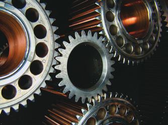
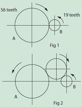
Take a look at the two gears meshing in Fig 1. The smaller gear will run at higher RPM than the larger one. Every time the large gear rotates one full revolution, all of its 56 teeth go past the smaller gear. As the gears are in mesh, this forces the smaller gear to revolve several times to make 56 teeth go past the same point. Calculations for the speed of gears are based around this formula:
RPM A No of Teeth Gear B
_____ = ________________
RPM B No of Teeth Gear A
By transposing this formula we can determine the speeds of gears or sizes of gears to give the desired RPM. Suppose in Figure 1 gear B is running at 1500 RPM. How fast will gear A run at?
RPM B x No Teeth Gear B 1500 x 19
RPM A = ______________________ = _______ = 509
No Teeth Gear A 56
Chain drive
The calculations for the speed of gears or sprockets using a chain drive are just the same. The length of the chain has no bearing on the relative speeds. It simply transfers the motion from one sprocket to the other. Similarly, if there is an idler gear between the two gears (Fig 2) it has no bearing on the speeds of gears A and B. Again, it just transfers the motion. However, it does reverse the direction of rotation
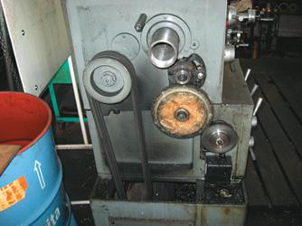
Belt drive
There are no teeth to count on the pulleys of a belt drive unless you are using a toothed belt (like a cambelt in a car engine). Instead, we use the diameters of the pulleys. In an ideal world, we would use a formula that would allow for some belt slippage. However, in the interests of simplicity and at the cost of a very small amount of accuracy, I use the formula below.
RPM A Diameter of Pulley B
______ = __________________
RPM B Diameter of Pulley A
Example:
I want pulley A to run at 800 RPM. Pulley B runs at 1500 RPM and is 6” (150 mm) outside diameter. What size must pulley A be?
By transposing the formula and substituting figures, we get
Dia. of pulley B x RPM B 6 x 1500
Dia. of pulley A = ______________________ = ________ = 11.25” (285 mm)
RPM A 800
If the size you have ended up calculating is not available, then select the closest size you have. Recalculate using that size to find out what RPM pulley A will run at.
Best drives?
Vee belt drives are one of the most common forms of drive with several advantages. They have smooth motion, are low-cost, quiet, have no lubrication required, can isolate shock loads, slip if there is an overload or stall, and have high efficiency (around 95 percent).
Chain drives have their own advantages. They are nonslip, can transmit more power for size, have a long service life, and can operate in hostile environments where there is high temperature, moisture, etc. Maintenance is easy.
Gear drives may be the most expensive, but they offer more. They are more compact, temperature- tolerant, transmit the most power, and have the longest service life with the least maintenance required. They are suitable where ratios need to be changed quickly during use. I know it all comes back to the budget and what you have available to hand. But it is good to think about what the ideal is so you can avoid using something totally inappropriate and wasting time.
There are new things in the pipeline too. Just look at the changes in drive systems on motorcycles. Not that long ago the roller chain was used exclusively, but look around now and you will see shaft drives with geared hubs and even rubber belt drives.
The Gates belt company in the USA have developed a belt drive for bicycles which has been given good reviews. From what I can determine, it has only been used in fixed ratio competition because gear-changing using these carbon-fibre belts has not been figured out yet.
I must admit that I would like to see a return to domestic rotary mowers having belt drives. Larger commercial ones do, but the regular mowers for home use are direct drives, with the blade bolted straight onto the crankshaft.
Okay, I am going back a huge number of years, but ask any seasoned lawnmower repairer how many bent crankshafts they have to deal with.
ROLLER CHAIN
There are two popular standards for roller chain for power transmission. The European or British
standard is covered by ISO606 and DIN8187 and the American standard is covered by ISO606, ANSI829.1 & DIN8188. The Japanese standard (JIS B 1801) is essentially the same as the American standard.
Surprisingly all three standards use imperial measurements and are very similar. It is important to check if you already have sprockets, which chain they are machined to suit as the roller sizes are different. For the same size of pitch in general the American standard chains have a smaller roller diameter. The pitch is the centre distance between rollers. For these chains, pitches range from 1/4”
(6.35 mm) to 3” (76.2 mm).
Swiss
The roller chain was invented and patented by Swiss engineer Hans Renold in 1880. The Renold
company is still a significant manufacturer of chain and sprockets in the world today.
Bicycle chains were made to these same standards originally but today are manufactured differently for derailleur geared bikes so that they can flex sideways during gear changes.
There are many other variations of roller chain such as hardened side plates, stainless steel, conveyor chain with long pitch, and chain with hollow pins or extended side plates for attaching parts. For more information take a look at:
www.renold.com,
www.didchain.com, and www.tsubakimoto.com.